3D-Printed Transformer Disappoints, But Enlightens

Transformers are deceptively simple devices. Just coils of wire sharing a common core, they tempt you into thinking you can make your own, and in many cases you can. But DIY transformers have their limits, as [Great Scott!] learned when he tried to 3D-print his own power transformer.

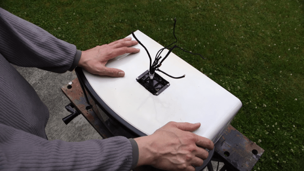
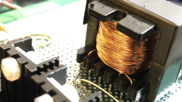
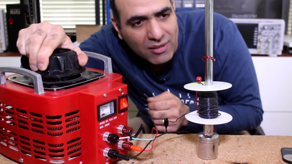
To be fair, the bulk of the video below has nothing to do with 3D-printing of transformer coils. The first part concentrates on building transformer cores up from scratch with commercially available punched steel laminations, in much the same way that manufacturers do it. Going through that exercise and the calculations it requires is a great intro to transformer design, and worth the price of admission alone. With the proper number of turns wound onto a bobbin, the laminated E and I pieces were woven together into a core, and the resulting transformer worked pretty much as expected.

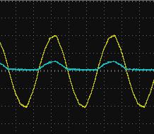
The 3D-printed core was another story, though. [Great Scott!] printed E and I pieces from the same iron-infused PLA filament that he used when he 3D-printed a brushless DC motor. The laminations had nowhere near the magnetic flux density of the commercial stampings, though, completely changing the characteristics of the transformer. His conclusion is that a printed transformer isn’t possible, at least not at 50-Hz mains frequency. Printed cores might have a place at RF frequencies, though.

In the end, it wasn’t too surprising a result, but the video is a great intro to transformer design. And we always appreciate the “DIY or Buy” style videos that [Great Scott!] does, like his home-brew DC inverter or build vs. buy lithium-ion battery packs.

Continue reading “3D-Printed Transformer Disappoints, But Enlightens”

Sniffed Transformer Puts Wired Doorbell Online

There’s certainly no shortage of “smart” gadgets out there that will provide you with a notification, or even a live audiovisual stream, whenever somebody is at your door. But as we’ve seen countless times before, not everyone is thrilled with the terms that most of these products operate under. Getting a notification on your phone when the pizza guy shows up shouldn’t require an email address, credit card number, or DNA sample.

For [Nick Touran], half the work was already done. There was already a traditional wired doorbell in his home, he just had to come up with a minimally invasive way to link it with Home Assistant. He reasoned that he could tap into the low-voltage side of the doorbell transformer and watch for the telltale fluctuations that would indicate the bell was doing its thing. The ESP8266 has an ADC to measure voltage and WiFi to connect to Home Assistant, so it seemed like the perfect bridge between old and new.

Transformer voltage before and after

Of course, as with any worthwhile project, it ended up being a bit more complicated. Wired doorbells generally operate on 16-24 VAC, and [Nick] knew if he tried to put his Wemos D1 across the line he’d release the critical Magic Smoke. What he needed was a voltage divider circuit that would take low-voltage AC and drop it to an even lower DC voltage that the microcontroller could cope with.

The simple circuit [Nick] comes up with cuts the voltage way down and removes the negative component completely. So what was originally 18.75 VAC turned into a series of 60 Hz blips at 2.4 VDC; perfect for feeding into a microcontroller ADC. With a baseline to work from, he could then write some code that would watch for variations in this signal to determine when the bell was ringing.

Or at least, that was the idea. While the setup worked well enough on the bench, its performance in the real-world left something to be desired. If his house guest had a heavy hand, it worked great. But a quick tap of the doorbell button would tend to go undetected. After investigating the issue, [Nick] found that he needed to use some software trickery to ensure the ESP8266 was able to keep up with the speedy signal. Once he was able to reliably detect short and long button presses, the rest was just a simple matter of sending an MQTT message to his automation system.

Compared to the hoops we’ve seen other hackers have to jump through to smarten up their doorbells, we think [Nick] got off fairly easy. This project is also an excellent example of how learning about circuit design and passive components can still come in handy in the Arduino Era.

Continue reading “Sniffed Transformer Puts Wired Doorbell Online”

A Lot Of Volts For Not A Lot

There was a time when high voltage in electronic devices was commonplace, and projects driving some form of vacuum or ionisation tube simply had to make use of a mains transformer from a handy tube radio or similar. In 2019 we don’t often have the need for more than a few volts, so when a Geiger–Müller tube needs a bit of juice, we’re stumped. [David Christensen] approached this problem by creating his own inverter, which can produce up to 1 kV from a 12 V supply.

Instead of opting for a flyback supply he’s taken a traditional step-up approach, winding his own transformer on a ferrite core. It has a centre-tapped primary which he drives in push-pull with a couple of MOSFETS, and on its secondary is a voltage multiplier chain. The MOSFETs take their drive at between 25 kHz and 50 kHz from a 555 timer circuit, and there is no feedback circuit.

It’s fair to say that this is a somewhat hair-raising circuit, particularly as he claims that it is capable of delivering that 1 kV at 20 W. It’s usual for high-voltage supplies driving very high impedance loads to incorporate a set of high-value resistors on their outputs to increase their internal impedance such that their danger is reduced. We’d thus exercise extreme care around this device, though we can see a lot of value in his description of the transformer winding.

We can’t criticise this circuit too much though, because some of us have been known to produce far hackier high voltage PSUs.

Visualizing Eddy Currents

If [Electroboom] gives up making videos and decides to become a lounge lizard in the Poconos, we hope he adopts the stage name Eddy Currents. However, he is talking about eddy currents in his recent video post that you can see below.

We know he doesn’t really think he can get the magnet to slow down with one sheet of aluminum foil and that he stages at least most of his little electric accidents, but we still enjoy watching it. Meanwhile, he also has a good explanation of why a copper pipe will slow down a magnet and how eddy current affects transformer efficiency.

Continue reading “Visualizing Eddy Currents”

A Look At Liquid Dielectrics

One evening quite a few years ago, as I was driving through my hometown I saw the telltale flashing lights of the local volunteer fire department ahead. I passed by a side road where all the activity was: a utility pole on fire. I could see smoke and flames shooting from the transformer and I could hear the loud, angry 60 Hz buzzing that sounded like a million hornet nests. As I passed, the transformer exploded and released a cloud of flaming liquid that rained down on the road and lawns underneath. It seemed like a good time to quit rubbernecking and beat it as fast as I could.

I knew at the time that the flaming liquid was transformer oil, but I never really knew what it was for or why it was in there. Oil is just one of many liquid dielectrics that are found in a lot of power distribution equipment, from those transformers on the pole to the big capacitors and switchgear in the local substation. Liquid dielectrics are interesting materials that are worth taking a look at.

Continue reading “A Look At Liquid Dielectrics”

This Is The Year Of PCB Inductors

It’s a story we’ve told dozens of times already. The cost to manufacture a handful of circuit boards has fallen drastically over the last decade and a half, which has allowed some interesting experiments on what PCBs can do. We’ve seen this with artistic PCBs, we’ve seen it with enclosures built out of PCBs, and this year we’re seeing a few experiments that are putting coils and inductors on PCBs.

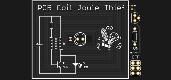
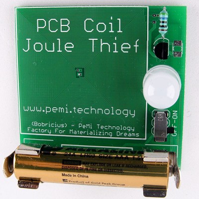
At the forefront of these experiments in PCB coil design is [bobricious], and already he’s made brushless and linear motors using only tiny copper traces on top of fiberglass. Now he’s experimenting with inductors. His latest entry to the Hackaday Prize is a Joule Thief, a simple circuit, but one that requires an inductor to work. If you want an example of what can be done with spirals of copper on a PCB, look no further than this project.

The idea was simply to make a Joule Thief circuit. The circuit is not complicated — you only need a transistor, resistor, and an inductor or transformer to boost the voltage from a dead battery enough to light up an LED.

The trick here is that instead of some wire wrapped around a ferrite or an off-the-shelf inductor, [bobricious] is using 29 turns of copper with six mil traces and spacing on a PCB. Any board house can do this, which means yes, you can technically reduce the BOM cost of a Joule Thief circuit at the expense of board space. This is the year of PCB inductors, what else should be be doing with creative PCB trace designs?

Repairing A Capacitor Inside A Potted Transformer

We always enjoy watching [Mr. Carlson’s] videos because he looks like he is taping in a rocket ship set from a 1950s drive-in movie. In a recent video, he identified an old oscilloscope that had a transformer assembly that is potted with a pair of capacitor inside. The capacitor failed so [Carlson] decided he would repair it. The problem? The transformer and capacitor are potted together with some sort of tar compound. You can see the result in the video below.

He actually didn’t know for sure the capacitor was really in the transformer, but they were in the schematic and by process of elimination, it had to be inside. Once he liberated the transformer, he did some tests to identify the capacitor before the depotting. The depotting takes a lot of heat and could damage the transformer, so he wanted to make sure it was really in there.

Continue reading “Repairing A Capacitor Inside A Potted Transformer”