A Bird 43 wattmeter and its homebrew equivalent

Homebrew Wattmeter Pays Homage To Sturdy Original

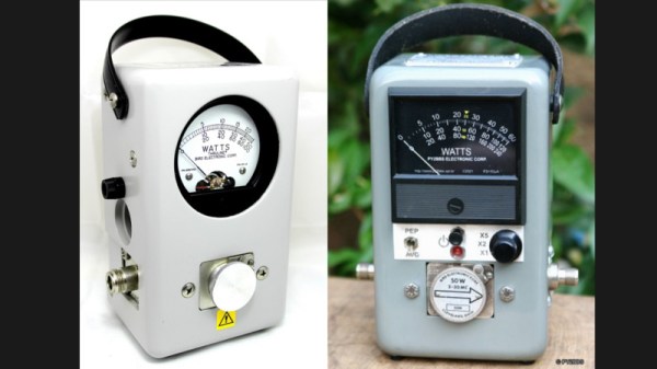
If there’s one instrument that hams and other radio enthusiasts covet, it’s the venerable Bird 43 Thruline wattmeter. The useful RF tool has barely changed in the nearly 70 years since it was first introduced, and they’re built like a tank. This makes Bird meters highly desirable, and therefore quite expensive either brand new or on the swap-meet circuit.

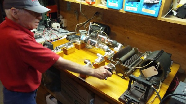
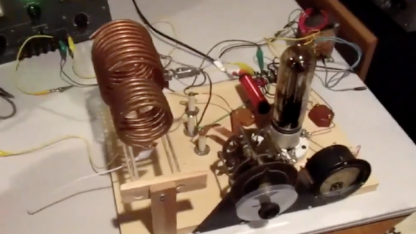
But radio amateurs are nothing if not resourceful, and building a homebrew version of the Bird wattmeter (in Portuguese; Google translate tool at the bottom of the page) as Brazilian ham [Luciano Sturaro (PY2BBS)] did is a good way to get your hands on one. Granted, [Luciano] had a head start: a spare line set, which is the important bit from a Bird wattmeter. The machined metal part is in effect an air-insulated section of coaxial cable that the RF signal passes through on its way from transmitter to antenna. A “slug” is inserted into the cavity in the line set to sense the RF and couple it to the meter electronics; the slug can be rotated to measure RF traveling in either direction, allowing the user to determine how much RF is getting reflected by the antenna system.

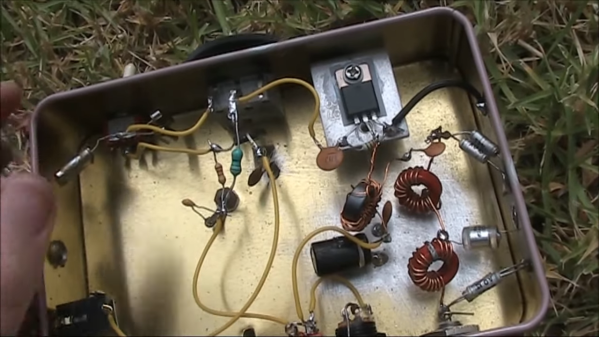
[Luciano]’s version of the meter is faithful to the sturdy construction of the original, with a solid steel case that mimics its classic lines — the case even sports the same color scheme and stout leather carry handle. There are some changes to the electronics, and the meter movement itself is different from the original, but all in all, the “Buzz 50” looks fantastic. We especially love the detailed nameplate as an homage to Bird.

The thing about Bird — and Bird-like — meters is that the slugs are like potato chips; you can’t have just one. Curious as to how these slugs work? Check out this slug repair project.

[Featured image of Bird 43 Wattmeter: Martin RF Supply]

Thanks to [Niko Huenk] for the tip!

Building A Hundred-Year-Old Radio Transmitter

Our Hackaday team is spread across the world, but remains in easy contact through the magic of the Internet. A number of us hold amateur radio callsigns, so could with a bit of effort and expenditure do the same over the airwaves. A hundred years ago this would have seemed barely conceivable as amateurs were restricted to the then-considered-unusable HF frequencies.

Thus it was that in December 1921 a group of American radio amateurs gathered in a field in Greenwich Connecticut in an attempt to span the Atlantic. Their 1.3 MHz transmitter using the callsign 1BCG seems quaintly low-frequency a hundred years later, but their achievement of securing reception in Ardrossan, Scotland, proved that intercontinental communication on higher frequencies was a practical proposition. A century later a group from the Antique Wireless Association are bringing a replica transmitter to life to recreate the event.

A free-running oscillator is today rarely seen in a radio transmitter, but at the time their single-tube Colpitts oscillator using a UV-204 transmitting tube would have been considered a stable source. That fed a 1KW power amplifier using three more UV-204s in parallel, which in turn fed a Marconi-style T antenna design with an earth counterpoise of multiple radial wires. The replica was originally built for an event in 1996, and substitutes the similar 204A tube for the now unobtainable UV-204. Even then, hundred-year-old tubes are hard to find in 2021, so they could only muster a single working example for the PA.

All in all it’s a very interesting project, and one of which we hope we’ll hear more as the anniversary approaches. If we can get the transmission details we’ll share them with you, and let’s see whether the same distances can be traversed with the more noisy conditions here in 2021.

To demonstrate how advanced this transmitter was for 1921, take a look at the Alexanderson alternator, its mechanical contemporary.

Getting On The Air With A 10-Minute-ish Ham Transmitter

Artificially constrained designs can be among the most challenging projects to build, and the most interesting to consider. The amateur radio world is no stranger to this, with homebrew radio designs that set some sort of line in the sand. Such designs usually end up being delightfully minimalist and deeply instructive of first principles, which is one reason we like them so much.

For a perfect example of this design philosophy, take a look at [VK3YE]’s twist on the classic “10-Minute Transmitter”. (Video, embedded below.)

The design dates back to at least the 1980s, when [G4RAW] laid down the challenge to whip up a working transmitter from junk bin parts and make a contact within 15 minutes — ten for the build and five for working the bands. [VK3YE] used the “oner” — one-transistor — design for his 10-minute transmitter, but invested some additional time into adding a low-pass filter to keep his signal clean, and a power amplifier to boost the output a bit.

Even with the elaborations, the design is very simple and easy to understand. Construction is the standard “ugly style” that hams favor for quick builds like this. There are no parts that would be terribly hard to find, and everything fits into a small metal box. The video below shows the design and build, along with some experiments with WebSDR receivers to check out range both with and without the power amplifier.

Seeing these kinds of builds really puts us in the mood for some low-power action. Could something like this pop up in “The $50 Ham” series? Quite possibly yes.

Continue reading “Getting On The Air With A 10-Minute-ish Ham Transmitter”

A One-Transistor Ham Transmitter Anyone Can Build

What attracts a lot of people to amateur radio is that it gives you the ability to make your own gear. Scratch-building hams usually start by making their own antennas, but eventually, the itch to build one’s own radio must be scratched. And building this one-transistor transmitter is just about the simplest way to dive into the world of DIY radio.

Of course, limiting yourself to eight components in total entails making some sacrifices, and [Kostas (SV3ORA)]’s transmitter is clearly a study in compromise. For starters, it’s only a transmitter, so you’ll need to make other arrangements to have a meaningful conversation. You’ll also have to learn Morse code because the minimalist build only supports continuous-wave (CW) mode, although it can be modified for amplitude modulation (AM) voice work.

The circuit is flexible enough that almost any part can be substituted and the transmitter will still work. Most of the parts are junk-bin items, although the main transformer is something you’ll have to wind by hand. As described, the transformer not only provides feedback to the transistor oscillator, but also has a winding that powers an incandescent pilot lamp, and provides taps for attaching antennas of different impedances — no external tuner needed. [SV3ORA] provides detailed transformer-winding instructions and shows the final build, which looks very professional and tidy. The video below shows the rig in action with a separate receiver providing sidetone; there’s also the option of using one of the WebSDR receivers sprinkled around the globe to verify you’re getting out.

This little transmitter looks like a ton of fun to build, and we may just try it for our $50 Ham series if we can find all the parts. Honestly, the hardest to come by might be the variable capacitor, but there are ways around that too.

Continue reading “A One-Transistor Ham Transmitter Anyone Can Build”

SDR Transmitting Gets The Power

Most hobby-grade software defined radio setups don’t transmit. Of the few that do, most of them put out anemic levels around one milliwatt or so. If you want to do something outside of the lab, you’ll need an amplifier and that’s what [Tech Minds] shows how to do in a recent video. (Embedded below.)

The video covers LimeSDR, HackRF, and the Pluto SDR, although the amplifiers should work with any transmitter. The SPF5189Z module is quite cheap and covers 50 MHz to 4 GHz, amplifying everything you throw at it. The downside is that it will amplify everything you throw at it, even parts of the signal you don’t want, such as spurs and harmonics.

Continue reading “SDR Transmitting Gets The Power”

Mobile Transmitter Gets Internal GPS And Bluetooth

While [Selim Olcer] was relatively happy with his Kenwood TM-D710a radio, he didn’t like the fact that it needed a bulky external GPS “backpack” for APRS location data. So he decided to crack open the head unit and see if he couldn’t integrate his own GPS hardware (machine translation). Not only did he succeed, but he even threw in Bluetooth compatibility for good measure.

With the repair manual circuit diagrams in hand, it was no problem to find the GPS RX and TX lines that were being broken out to the external connector. Unfortunately, the radio’s electronics are all 5 volts and the GPS module [Selim] wanted to use was only 3.3 V. So he came up with a small PCB that included not only the voltage regulator to power the GPS module, but also some voltage-dividers to level shift those signals.

Since the Kenwood TM-D710a was already designed to accept a GPS upgrade module, he just needed to change some configuration options in the radio’s menus for it to see the new hardware. Technically the project was done at this point, but since there was still room in the case and he had a GPS module spitting out NMEA sentences, [Selim] tacked on a common Bluetooth serial module so he could see the position information on his smartphone. With an application like APRSdroid, he now has a nice moving map display using the position pulled from the radio’s GPS.

With this modification done it looks like the head unit is ready to go, but that’s only the beginning for a mobile rig. Now we want to see how he integrates the whole thing into the car.

Hacking Transmitters, 1920s Style

The origin of the term “breadboard” comes from an amusing past when wooden bread boards were swiped from kitchens and used as a canvas for radio hobbyists to roll homemade capacitors, inductors, and switches. At a period when commercial electronic components were limited, anything within reach was fair game.

[Andy Flowers], call sign K0SM, recently recreated some early transmitters using the same resources and techniques from the 1920s for the Bruce Kelley 1929 QSO Party. The style of the transmitters are based on [Ralph Hartley]’s oscillator circuit built for Bell Telephone in 1915. Most of the components he uses are from the time period, and one of the tubes he uses is even one of four tubes from the first Transatlantic contact in 1923.

Apart from vacuum tubes (which could be purchased) and meters (which could be scrounged from automobiles) [Flowers] recreated his own ferrite plate and outlet condensers for tuning the antennas. The spiderweb coils may not be as common today, but can be found in older Crosley receivers and use less wire than comparable cylindrical coils.

A number of others features of the transmitters also evoke period nostalgia. The coupling to the antenna can be changed using movable glass rods, although without shielding there are quite a number of factors to account for. A vertical panel in the 1920s style also shows measurements from the filament, plate current, and antenna coupling.

While amature radio has become increasingly high-tech over the last few years, it’s always good to see dedicated individuals keeping the old ways alive; no matter what kind of technology they’re interested in.

Continue reading “Hacking Transmitters, 1920s Style”