Tube Design Tips To Save A Writer’s Project

Most of the stories we cover here are fresh from the firehose, the newest and coolest stuff to interest you during your idle moments. Sometimes though, we come across a page that’s not new, but is interesting in its own right enough to bring to your attention. So it is with our subject here, because when faced with a tube circuit design problem, we found salvation in a page from [The Valve Wizard].

Do you need to apply negative feedback to a triode amplifier? The circuit is simplicity itself, but sadly when we were at university they had long ago stopped teaching the mathematics behind the component values. Step forward everything you need to know about triode amplifier negative feedback.

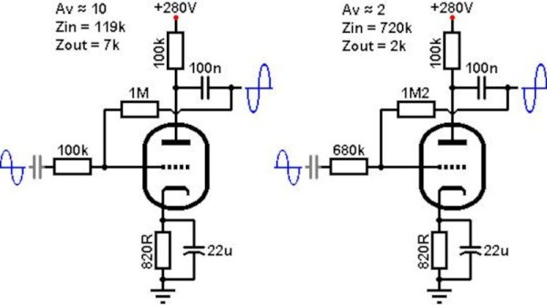
Negative feedback is a pretty simple idea: subtract a little of the amplifier’s output from the input. It reduces the amplifier’s gain with a flat response, so it’s useful for removing humps in the frequency response and reducing the tendency for distortion. In a single-ended triode amp it’s done with a resistor and capacitor from anode to grid, but the question is, just what resistor or capacitor?. Here the page has all the answers, taking the reader through calculating the desired gain, and picking the value of the capacitor to avoid affecting the frequency response. We wish that someone had taught us this three decades ago!

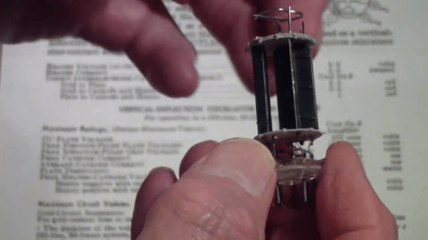
The website is full of really useful info about valve or tube amps, and it’s worth mentioning that he’s made it available in book format too. There’s no reason not to have a go at vacuum electronics. Meanwhile in case you are wondering what project prompted this, it was a quest to improve upon this cheap Chinese kit amplifier.

Reshoring Vacuum Tube Manufacturing, One Tube At A Time

For most of us, vacuum tubes haven’t appeared in any of our schematics or BOMs in — well, ever. Once mass-manufacturing made reliable transistors cheap enough for hobbyists, vacuum tubes became pretty passe, and it wasn’t long before the once mighty US tube industry was decimated, leaving the few remaining tube enthusiasts to ferret out caches of old stock, or even seek new tubes from overseas manufacturers.

However, all that may change if [Charles Whitener] succeeds in reshoring at least part of the US vacuum tube manufacturing base. He seems to have made a good start, having purchased the Western Electric brand from AT&T and some of its remaining vacuum tube manufacturing equipment back in 1995. Since then, he has been on a talent hunt, locating as many people as possible who have experience in the tube business to help him gear back up. Continue reading “Reshoring Vacuum Tube Manufacturing, One Tube At A Time”

JFET Stands In For Triode In This Infinite Impedance Detector

An “Infinite Impedance Detector” might sound a little like something that [Zaphod Beeblebrox] would use to zip around the galaxy. It’s not, of course, but it is an interesting and useful demodulator for AM radio signals, as [Sebastian Westerhold] over at Baltic Labs explains in the brief but well-done video below.

If you’ve ever browsed through schematics of old vacuum tube radios, [Sebastian]’s JFET-based detector circuit might look strangely familiar. That’s because this demodulator is about as close to a direct translation between a vacuum tube circuit and a silicon circuit as possible. In fact, [Sebastian] even used literature from the triode version of this detector to figure out the values for some of the components. The only active component is a BF256B JFET; the rest are a small handful of resistors and caps. Construction is in the ever-popular ugly style.

The test setup is simple — a function generator set to 455 kHz and modulated with a 1,000 Hz sine wave. The detector demodulates the audio signal very cleanly, judging by the oscilloscope traces. Just for fun, [Sebastian] also tried a 10.7 MHz carrier with a 1,500 Hz audio modulation, and that worked fine too. He also tried a variation on the circuit with an IF transformer on the input. That circuit works just about the same as the transformerless version, although it does provide a little gain.

Earth-shattering stuff? Probably not. But it does show the fun you can have with a scrap of PCB and a few components, and seems like it could easily be the kind of project that would take you down the RF rabbit hole. Thanks to [Sebastian] for sharing this one with us.

Continue reading “JFET Stands In For Triode In This Infinite Impedance Detector”

A Homemade Tube Amplifier Featuring Homemade Tubes

With the wealth of cheap and highly integrated audio amplifier modules on the market today, it takes a special dedication to roll your own from parts. Especially when those parts include vacuum tubes, and doubly so when you make the vacuum tubes from scratch too.

Now, we get it — some readers are going to find it hard to invest an hour in watching [jdflyback] make a pair of triodes to build his amplifier. But really, you’ve got to check this out. Making vacuum tubes with all the proper equipment — glassblower’s lathe, various kinds of oxy-fuel torches, all the right hand tools — is hard enough. But when your lathe is a cordless drill, and you’re using a spot welder that looks like it’s cobbled together from junk, your tube-making game gets a lot harder. Given all that, you’d expect the tubes to look a lot rougher than they are, but even with plain tungsten wire heaters and grids made from thick copper wire, they actually work pretty well. Sure, the heaters glow as bright as light bulbs, but that’s all part of the charm.

Speaking of charm, we just love the amp these tubes went into. Built in 1920s breadboard-style, the features some beautiful vintage mica capacitors and wirewound resistors, plus a variable resistor the likes of which we’ve never seen. The one nod to modernity is the clever use of doorbell transformers, one for a choke and one for the speaker transformer. They don’t sound great, but there’s no doubt they work.

We may have seen other homemade vacuum tubes before — we even recently featured a DIY X-ray tube — but there’s something about [jdflyback]’s tubes that really gets us going.

Continue reading “A Homemade Tube Amplifier Featuring Homemade Tubes”

Reverse Engineering A Module From A Vacuum Tube Computer

It’s best to admit upfront that vacuum tubes can be baffling to some of the younger generation of engineers. Yes, we get how electron flow from cathode to anode can be controlled with a grid, and how that can be used to amplify and control current. But there are still some things that just don’t always to click when looking at a schematic for a tube circuit. Maybe we just grew up at the wrong time.

Someone who’s clearly not old enough to have ridden the first wave of electronics but still seems to have mastered the concepts of thermionic emission is [Usagi Electric], who has been doing some great work on reverse engineering modules from old vacuum tube computers. The video below focuses on a two-tube pluggable module from an IBM 650, a machine that dates clear back to 1954. The eBay find was nothing more than two tube sockets and a pair of resistors joined to a plug by a hoop of metal. With almost nothing to go on, [Usagi] was still able to figure out what tubes would have gone in the sockets — the nine-pin socket was a big clue — and determine that the module was likely a dual NAND gate. To test his theory, [Usagi] took some liberties with the original voltages used by IBM and built a breakout PCB. It’s an interesting mix of technologies, but he was able to walk through the truth table and confirm that his module is a dual NAND gate.

The video is a bit long but it’s chock full of tidbits that really help clear up how tubes work. Along with some help from this article about how triodes work, this will put you on the path to thermionic enlightenment.

Continue reading “Reverse Engineering A Module From A Vacuum Tube Computer”

Decapsulating A Dual Triode

We see quite a bit of work where people decapsulate ICs or other solid state devices to expose their inner workings. But how about hollow state? [Tomtektest] had a dual triode that has lost its vacuum integrity — gone to air, as he calls it — and decided to open it up to better expose its inner workings. (Video, embedded below.)

Of course, you can always see the innards through the glass, but it is interesting to have the envelope out of the way. Apparently, how you remove the glass is a bit tricky if you don’t want to damage the working bits as you remove it.

Continue reading “Decapsulating A Dual Triode”

Fleming and De Forest Rectifier Patents

The History And Physics Of Triode Vacuum Tubes

The triode vacuum tube might be nearly obsolete today, but it was a technology critical to making radio practical over 100 years ago. [Kathy] has put together a video that tells the story and explains the physics of the device.

The first radio receivers used a device called a Coherer as a detector, relying on two tiny filaments that would stick together when RF was applied, allowing current to pass through. It was a device that worked, but not reliably. It was in 1906 that Lee De Forest came up with a detector device for radios using a vacuum tube containing a plate and a heated filament. This device so strongly resembled the Fleming Valve which John Fleming had patented a year before, that Fleming sued De Forest for patent infringement.

After a bunch of attempts to get around the patent, De Forest decided to add a third element to the tube: the grid. The grid is a piece of metal that sits between the filament and the plate. A signal applied to the grid will control the flow of electrons, allowing this device to operate as an amplifier. The modification created the triode, and got around Fleming’s patent.

[Kathy]’s video does a great job of taking you through the creation of the device, which you can watch after the break. She also has a whole series on the history of electricity, including a video on the Arc Transmitter which we featured previously.

Continue reading “The History And Physics Of Triode Vacuum Tubes”