Picture of the modification as it's being performed, with an extra chip stacked on top of the original, extra magnet wire connection going to the chip select line pin

Original XBox V1.6 RAM Upgrade Stacks TQFP Chips

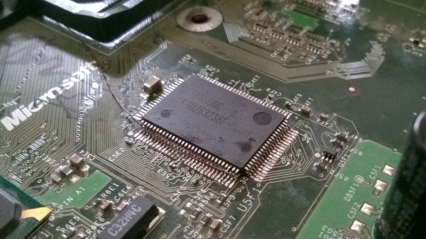
RAM upgrades for the original XBox have been a popular mod — you could relatively easily bump your RAM from 64MB to 128MB. While it wouldn’t give you any benefit in most games written to expect 64MB, it does help with emulators, game development, and running alternative OSes like Linux. The XBox PCB always had footprints for extra RAM chips, so RAM upgrades were simple – just get some new RAM ICs and solder them onto the board. However, in the hardware revision 1.6, these footprints were removed, and RAM upgrades on v1.6 were always considered impossible.

[Prehistoricman] brings a mod that makes RAM upgrades on v1.6 possible using an old trick from the early days of home computers. He’s stacking new RAM chips on top of the old ones and soldering them on in parallel. The overwhelming majority of the RAM lines are shared between chips, which is what makes this mod possible – all you need to connect to the extra chips is magnet wire for extra RAM chip select lines, which are, thankfully, still available on the board. He shares a tutorial with plenty of illustrations, so it should be easier for you to perform this mod, in case you’re stuck with a newer console that doesn’t have the RAM chip footprints left onboard.

We just covered an original XBox softmodding tutorial, so this is as timely as ever! If you’re looking to read about the 128MB mod, this is a good place to start.

We thank [DjBiohazard] for sharing this with us!

Soldering Challenge To Challenge You

[Rick] knew that the blinking, beeping microcontroller kits that are commonly used for educational soldering workshops just would not cut it for a serious combat among SMD reworking professionals. The “Soldering Challenge” he created to fill this gap is a little PCB with eight difficulty levels from large through hole components to the smallest hand solderable SMDs. After assembly, the circuit assesses the skill level of the soldering aspirant based on a built-in scoring system.

soldering_challenge_ongoingThe challenge is meant to be played on a time limit. There are no two same-sized components of different value, so contestants may focus on soldering fast. Little rubber pads on the backside of the board provide for good ground contact in the curves. After the starting signal, you will be confronted with a few through hole resistors, a capacitor, different LEDs and a DIP-8 IC. Here it’s all about the speed and efficiency as you tackle a track full of bends and cut-off resistor legs. Over the course of the challenge, the components get smaller and smaller, until you finally reach the 0603 level, with a tiny SC-85 MOS-FET and a TSSOP 555 timer at the finishing line.
Continue reading “Soldering Challenge To Challenge You”

Soldering Small Components For A Video DA

Video DA Board

Video distribution amplifiers are used to amplify a video signal and split it into multiple outputs so multiple displays can be driven. They are also used to correct the gain of an incoming video signal. [Andrew] was having trouble with the video signal from an interferometer, and found the issue was caused by a low output gain. His solution was to build his own video distribution amplifier.

The THS7374 appeared to be the perfect chip for this application. It’s a four channel video amplifier IC, and only requires a few passive components to run. The only problem was the package: a 14 pin TSSOP with 0.65 mm pitch. Not fun to solder by hand, especially if you don’t have a PCB.

[Andrew]’s solution was to build his own breakout out of copper-clad board. He worked under a microscope and cut out a pattern for the part, then soldered 30 AWG wire to the pins to make connections. After cleaning off any copper that could cause a short, the board was working, and the video waveform looked great on an oscilloscope.

After testing, even more gain was needed. [Andrew] ended up cascading two of the amplifiers. This method of prototyping doesn’t look easy, but could be worth it when you need a single board.

Launchpad Not Limited To Value Line Chips

Wanting to use my TI Launchpad as more than just a development board I thought I’d do a few experiments using it as an in-system programmer. After a few tripping points I was able to get it working and then some. It seems that the device is not limited to just the value line of microcontrollers it was intended to support. In the image above I’m using it to program an MSP430F2272 which is a pretty powerful little chip with 32 KB of program space. Click through the break for more information on the setup.

Continue reading “Launchpad Not Limited To Value Line Chips”