Vintage Plotter Gets Bluetooth Upgrade

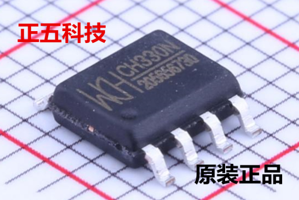
Recently [iot4c] stumbled upon this gorgeous Robotron Reiss plotter from 1989, brand-new and still in its original box. Built before the fall of the Berlin Wall in East Germany, it would be a crime to allow such a piece of computing history to go unused. But how to hook it up to a modern system? Bad enough that it uses some rather unusual connectors, but it’s about to be 2020, who wants to use wires anymore? What this piece of Cold War hardware needed was an infusion of Bluetooth.

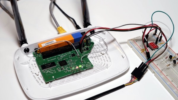
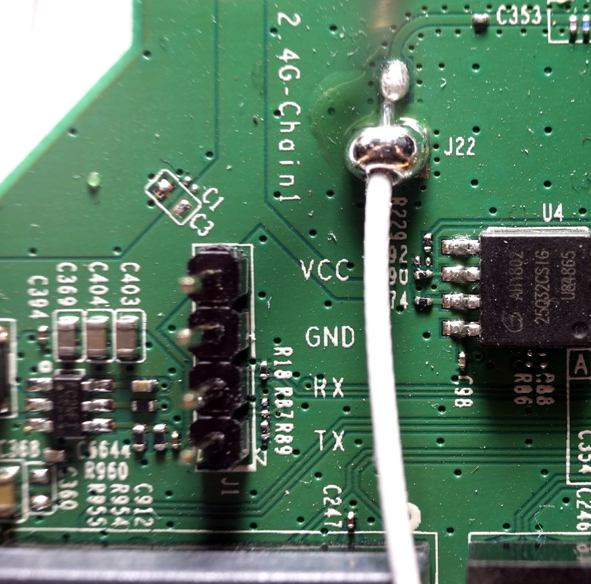
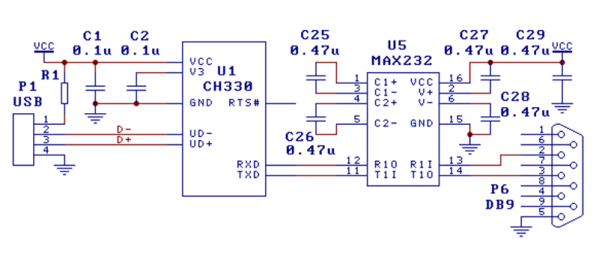
While the physical ports on the back of the Robotron certainly look rather suspect, it turns out that electrically they’re just RS-232. In practice, this means converting it over was fairly straightforward. With a Bolutek BK3231 Bluetooth module and an RS-232 to UART converter, [iot4c] was able to create a wireless adapter that works transparently on the plotter by simply connecting it to the RX and TX pins.

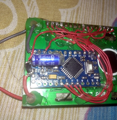
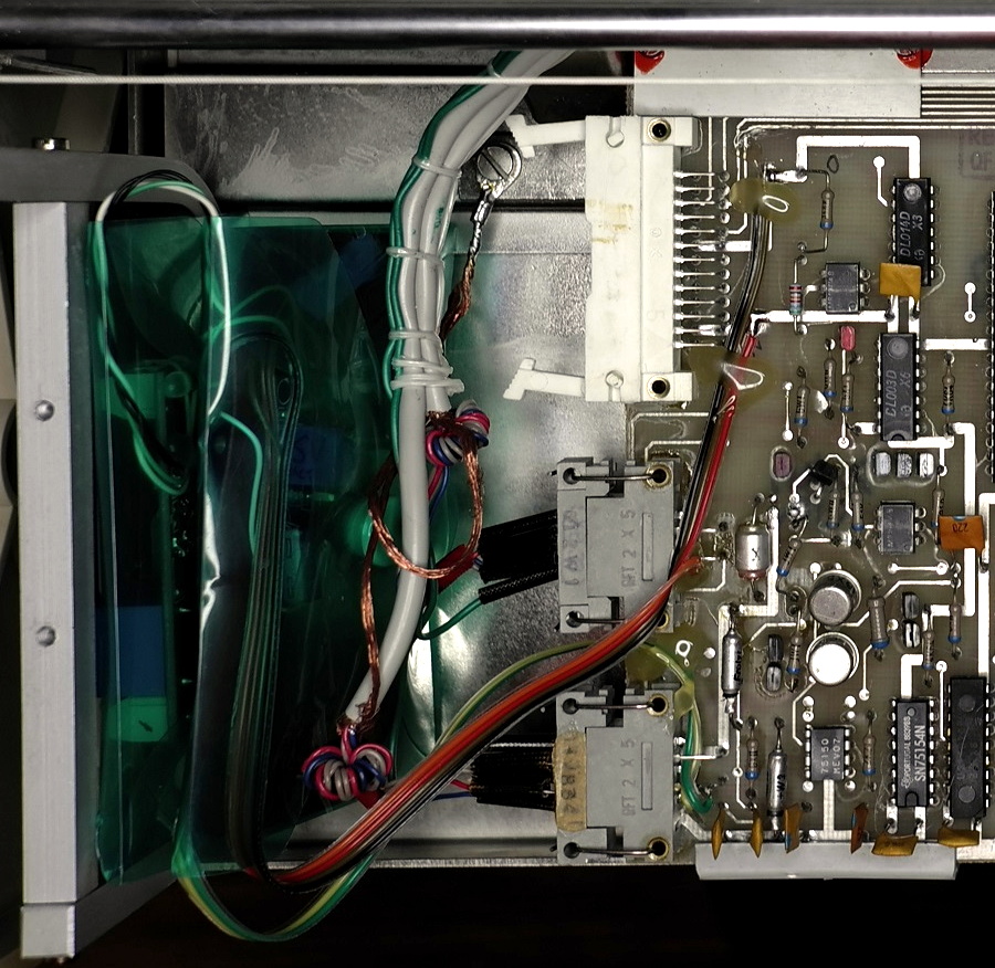
A small DC buck converter was necessary to provide 3.3 V for the Bluetooth adapter, but even still, there was plenty of room inside the plotter’s case to fit everything in neatly. From the outside, you’d have no idea that the hardware had ever been modified at all.

But, like always, there was a catch. While Windows had no trouble connecting to the Bluetooth device and assigning it a COM port, the 512 byte buffer on the plotter would get overwhelmed when it started receiving commands. So [iot4c] wrote a little script in Node.js that breaks the commands down into more manageable chunks and sends them off to the plotter every 0.1 seconds. With this script in place the Robotron moved under its own power for the first time in ~30 years by parsing a HP-GL file generated by Inkscape.

If you’re interested in a plotter of your own but don’t have a vintage one sitting around, never fear. We’ve seen an influx of DIY plotters recently, ranging from builds that use popsicle sticks and clothespins to customizable 3D printed workhorses.

Dissecting The TL-WR841N For Fun And Profit

The TP-Link TL-WR841N isn’t a particularly impressive piece of hardware, but since it works decently well and sells for under $20 USD, it’s one of the most popular consumer routers on Amazon. Now, thanks to [TrendyTofu] of the Zero Day Initiative, we now have a concise step-by-step guide on how to hack your way into the newer versions of the hardware and take full control over this bargain WiFi device. This work was initially done to help test out reported vulnerabilities in the router’s firmware, but we’re sure the readers of Hackaday can come up with all sorts of potential uses for this information.

TP-Link helpfully labeled the UART pins

The story starts, as so many before it have, with a serial port. Finding the UART pads on the PCB and wiring up a level shifter was no problem, but [TrendyTofu] found it was only working one-way. Some troubleshooting and an oscilloscope later, the culprit was found to be a 1kΩ pull down resistor connected to the RX line that was keeping the voltage from peaking high enough to be recognized.

Once two-way communication was established, proper poking around inside the router’s Linux operating system could begin. It wasn’t a huge surprise to find the kernel was ancient (version 2.6.36, from 2010) and that the system utilities had been stripped to the absolute bare minimum to save space. Replacing the firmware entirely would of course be ideal, but unfortunately OpenWRT has dropped support for the newer hardware revisions of the TL-WR841N.

To teach this barebones build of Linux some new tricks, [TrendyTofu] used the mount command to find a partition on the system that actually had write-access, and used that to stash a pre-compiled build of BusyBox for MIPS. With a more complete set of tools, the real fun could begin: using GDB to debug TP-Link’s binaries and look for chinks in the armor. But feel free to insert your own brand of mayhem here.

You might think that in the era of the Raspberry Pi, abusing cheap routers to turn them into general purpose Linux boxes would be somewhat out of style. Frankly, you’d be right. But while the days of strapping Linksys WRT54Gs to remote controlled cars might be long be gone, there are still some routers out there interesting enough to make it worth dusting off this time-honored hardware hacker tradition.

Driving A 16×2 LCD With Voltage Modulation

The basic 16×2 LCD is an extremely popular component that we’ve seen used in more projects than we could possibly count. Part of that is because modern microcontrollers make it so easy to work with; if you’ve got an I2C variant of the display, it only takes four wires to drive it. That puts printing a line of text on one of these LCDs a step or two above blinking an LED on a digital pin on the hierarchy of beginner’s electronics projects.

What’s that? Even four wires is too many? In that case, you might be interested in this hack from [Vinod] which shows how you can drive the classic 16×2 with data and power on the same pair of wires. You’ll still need a microcontroller “backpack” for the LCD to interpret the modulated voltage, but if you’ve got an application for a simple remote display, this is definitely worth checking out.

The basic idea is to “blink” the 5 V line so quick that a capacitor on the LCD side can float the electronics over the dips in voltage. As long as one of the pins of the microcontroller is connected to the 5 V line before the capacitor, it will be able to pick up when the line goes low. With a high enough data rate and a large enough capacitor as a buffer, you’re well on the way to encoding your data to be displayed.

For the transmitting side, [Vinod] is using a Python script on his computer that’s sending out the text for the LCD over a standard USB to UART converter. That’s fed into a small circuit put together on a scrap of perfboard that triggers a MOSFET off of the UART TX line.

We actually covered the theory behind this technique years ago, but it’s always interesting to see somebody put together a real-world example. There might not be too many practical uses for this trick in the era of dirt-cheap microcontrollers bristling with I/O, but it might make a fun gag at your hackerspace.

Continue reading “Driving A 16×2 LCD With Voltage Modulation”

ATtiny Gets A Tiny Software UART

Modern microcontroller platforms spoil us with their performance and expansive spec sheets. These days it’s not uncommon to be developing for a cheap micro that has a clock rate well in excess of 100MHz, with all manner of peripherals baked in. DACs, WiFi, you name it – it’s in there, with a bunch of libraries to boot. It wasn’t always this way, and sometimes you would even find yourself lacking hardware serial support. In these cases, the bitbanged software UART is your friend, and [MarcelMG] decided to document just how it’s done.

The amateur programmer’s first recourse may be to use delays to properly time the output data stream. This has the drawback of wasting processor cycles and doesn’t let the microcontroller do much else useful. Instead, [Marcel] discusses the proper way to do things, through the use of interrupt service routines and hardware timers.

[Marcel]’s implementation is for the ATtiny24A, though it should be easily portable to other AVR8 processors. Taking up just 2 bytes of RAM and 276 bytes of program space, it’s compact – which is key on resource-limited 8-bit devices. The code is available on Github if you fancy trying it out yourself.

It’s a technique that is more than familiar to the old hands, but useful to those new to the art. It can be particularly useful if you need to get data out of a legacy platform with limited options. As times change, it’s important to pass on the techniques of yesteryear to the new generation. Of course, if things are really tight, you can even do a half-duplex UART on a single pin.


Pi Zero Gives Amateur Astronomer Affordable Control Of Telescope

Like many other hobbies, astronomy can be pursued on many levels, with equipment costs ranging from the affordable to the – well, astronomical. Thankfully, there are lots of entry-level telescopes on the market, some that even come with mounts that automatically find and track heavenly bodies. Finding a feature is as easy as aligning to a few known stars and looking up the object in the database embedded in the remote.

Few of the affordable mounts are WiFi-accessible, though, which is a gap [Dane Gardner]’s Raspberry Pi interface for Celestron telescopes aims to fill. For the price of a $10 Pi Zero W and a little know-how, [Dane] was able to gain full control over his ‘scope. His instrument is a Celestron NexStar, a Schmidt-Cassegrain reflector with a 150-mm aperture, has a motorized altitude-azimuth mount. The handheld remote had enough room for him to add the Zero, powering it from the mount’s battery pack. The handset has an RS-232 serial port built-in, but with the level differences [Dane] just connected the Pi directly to the handset before the UART. Running INDI, a cross-platform astronomical instrument control library, he now has total control of the scope, and he can use open source astronomy software rather than the limited database within the handset. As a neat side trick, the telescope can now be controlled with a Bluetooth gamepad.

Astronomy and electronics go hand in hand, whether in the optical or radio part of the spectrum. We like the way [Dane] was able to gain control of his telescope, and we’d like to hear about what he sees with his new tool. Assuming the Seattle weather ever cooperates.

Continue reading “Pi Zero Gives Amateur Astronomer Affordable Control Of Telescope”

“DB” = Abbreviated Microcontroller Debugging

We’ve all been there. When debugging a microcontroller project, we just want to put in a print statement to figure out what’s going on with the microcontroller in real time. However, advanced embedded programmers know that printf statements are verboten: they’re just too SLOW. While not fixing this plight entirely, [Atakan Sarioglu] has come up with a clever way to create readable debug messages with minimal runtime overhead.

[Atakan Sarioglu]’s innovation, called BigBug (Github), is a dynamically-generated codebook. The codebook translates abbreviated messages sent over serial (UART here) to longer-form human-readable messages. To generate the codebook, BigBug automatically parses your comments to create a lookup between an abbreviation and the long-form message. When you are running your program on the microcontroller, BigBug will translate the short codes to long messages in real-time as you send log/debug data over serial. Continue reading ““DB” = Abbreviated Microcontroller Debugging”

New Part Day: The Fifty Cent USB Chip

If you want to plug a USB cable into your next project, you’ve got a problem. USB is not UART, and UART is what every microcontroller serial port wants. To add USB to your microcontroller project, you’ll need to add a support chip, probably from FTDI, although there are a multitude of almost-FTDI clones available from the other parts of the Internet. These parts are slightly expensive, and they require some support circuitry. What you really need is a simple device that requires minimal external components, takes in serial from your microcontroller and spits out USB, and costs no more than a dollar. Bonus points if it’s hand-solderable.

The CH330 is apparently the answer to this problem (That’s a TaoBao link, this is probably going to be the best link going forward). It’s a dead simple chip with eight pins. Two are the data lines on a USB cable, and two are TX and RX for your microcontroller. The other pins are just power, ground, and an RTS line. Best of all, it only costs about fifty cents. You’ve never heard about it, because a few hours after this post is published, it will be the most information you’re going to get on this chip in the English-speaking world.

As far as we can tell, the CH330 is the smallest in a line of USB to UART converters from WCH, although the part isn’t even on the company’s website. The first reference to the phrase ‘CH330’ in reference to a USB chip appeared about a month ago, at the beginning of September. There’s a GitHub for someone who is apparently using this chip in a Pine64 board, but that’s about it. There’s no more information.

Right now, the only documentation for this chip is a single Chinese-language datasheet with an example schematic showing this chip connected to a MAX232 as a USB to RS232 converter. This is it. You’re looking at all the information that exists on this chip in the English-speaking version of the Internet.

The idea of a cheap, small chip that easily turns USB into UART would be great for thousands of projects. An FTDI chip will work, yes, but if you’re making thousands of a thing you might want to go with the fifty cent part over the two dollar part. That said, we’re in untested waters with this part, and you can’t even find it on AliExpress.

Let us know if you’ve gotten your hands on one of these devices. This has the potential to be really useful in a lot of projects and products, and we’re eager to see what the community comes up with. Thanks to [acabx] for sending this one in on the tip line.