As soon as a project involves other assemblies, parts, or modules, things get more complicated. Devices like fans, cooling units, probes, pumps, or lighting might have simple electrical requirements, but they are rarely identical. As a result, one’s tidy project ends up having to deal with, for example, a pump that is controlled with 5 V active high logic, a sensor that outputs 5 V active low, lights that expect to be switched with 24 VDC, and a fan that needs a relay right now. But that might change in the future.
That’s exactly what led [Lukas Fässler] to design and build the Universal Interface, a board intended to be a kind of universal translator and interface for all such devices. The idea is to have one Universal Interface board for every external device. For each board, a wide variety of input combinations controls a single output. The boards are “hardware programmable” in the sense that jumpers (zero-ohm resistors) are used to spell out in black and white exactly what combinations of inputs result in which output state. In this way, some standardization and clarity of control can be enforced while still being flexible enough to accommodate changes.
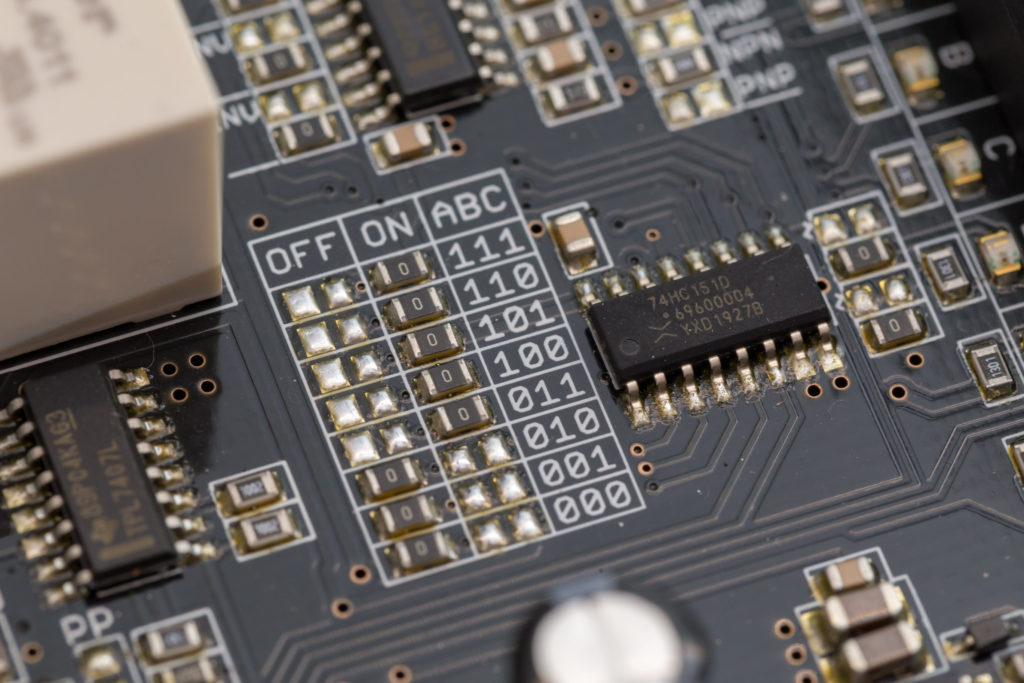
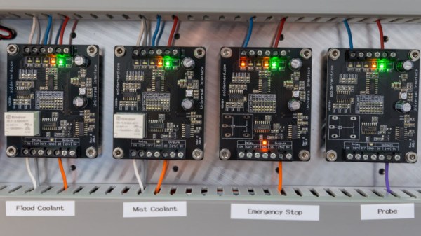
Each Universal Interface board has three inputs and an enable line, each with their own indicator LED visually confirming its state. The inputs are 24 V tolerant and each can be configured with a pull-up, a pull-down, and as an active high or active low. There is one output, but it takes several forms: a sturdy relay, a powerful open-collector output, a 5 V logic output, and a 24 V logic output. Configuring which output state corresponds to what combination of inputs is set by jumpers, so the board is very much WYSIWYG.
[Lukas] is currently using four of these devices with his CNC mill project, all in different configurations, and they’re working reliably. Interested? The GitHub repository for the project has all the board design files.


