USB-C Charging Mod Brings In The Juice

By now we’re well under way with the consolidation of low-voltage power supplies under the USB-C standard, and the small reversible connector has become the de facto way to squirt some volts into our projects. But for all this standardization there are still a few places where the harmony of a unified connector breaks down, and things don’t work quite the way they are supposed to. One such case has occupied [James Ide] — devices which will accept power from a USB-A to USB-C cable, but not from a USB-C to USB-C one. His solution? A small flexible PCB upgrade.

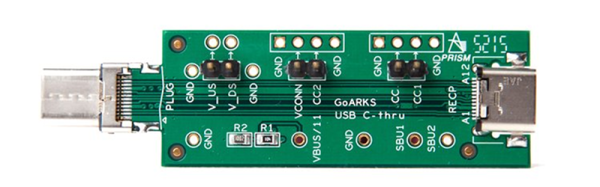
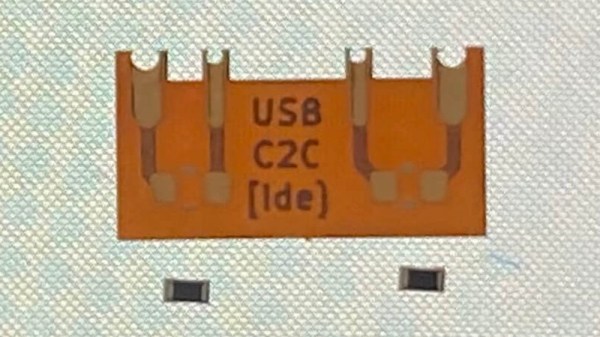
The problem lies with how different power supplies and peripherals identify each other, and quite likely in device manufacturers skimping on a few components here and there. A compliant USB-C power supply expects to see pull-down resistors on the data lines, and will thus refuse to serve power to devices that don’t possess them. Meanwhile the USB-A supply will quite happily serve juice without such checks, which is what the manufacturer is relying on. The solution is a tiny flexible PCB with the resistors, designed to be retrofitted behind a USB-C socket. On one hand it’s probably one of the simplest circuits we’ve ever shown you, and on the other it’s a cleverly designed solution to the issue at hand.

If the nitty-gritty of USB-C interests you, then we’ve taken a much closer look in the past.

Thanks to [Andrea] for the tip.

A Close Look At USB Power

It’s not a stretch to say that most devices these days have settled on USB as their power source of choice. While we imagine you’ll still be running into the occasional wall wart and barrel jack for the foreseeable future, at least we’re getting closer to a unified charging and power delivery technology. But are all USB chargers and cables created equal?

The answer, of course, is no. But the anecdotal information we all have about dud USB gear is just that, which is why [Igor Brkić] wanted to take a more scientific approach. Inspired by the lighting bolt icon the Raspberry Pi will flash on screen when the voltage drops too low, he set out to make a proper examination of various USB chargers and cables to see which ones aren’t carrying their weight.

In the first half of his investigation, [Igor] tests four fairly typical USB chargers with his TENMA 72-13200 electronic load. Two of them were name brand, and the other just cheap clones. He was surprised to find that all of the power supplies not only met their rated specifications, but in most cases, over-performed by a fair amount. For example the Lenovo branded charger that was rated for only 1 A was still putting out a solid 5 V at 1.7 A. Of course there’s no telling what would happen if you ran them that high for hours or days at a time, but it does speak to their short-term burst capability at least.

He then moved onto the USB cables, were things started to fall apart. The three generic cables saw significant voltage drops even at currents as low as 0.1 A, though the name brand cable with 20 AWG power wires did fare a bit better. But by .5 A they were all significantly below 5 V, and at 1 A, forget about it. Pulling anything more than that through these cables is a non-starter, and in general, you’ll need to put at least 5.2 V in if you want to actually run a USB device on the other side.

Admittedly this might not be groundbreaking research, but we appreciate [Igor] taking a scientific approach and tabulating all the information. If you’re still getting low voltage warnings on the Pi after swapping out your cheapo cables, then maybe the problem is actually elsewhere.

New Part Day: Sonoff USB Smart Adaptor Taps A New WiFi Chip

For decades, we dreamt of a future where all of our electronics used a standardized power connector. Most of us probably didn’t expect that USB would ultimately fill that role, but we’ll take what we can get if it means a future without getting a new wall wart for every piece of tech we buy. From soldering irons to laptops, the number of things you can power with a lowly USB cable these days is pretty incredible.

Which makes it all the more surprising it took so long for somebody to come up with a way to toggle USB devices off and on over the network. The Sonoff “USB Smart Adaptor”, which the company says will start shipping before the end of the year, is the logical evolution of their exceptionally popular mains voltage smart switches. The Smart Adapter is designed to go between the device and its existing power supply, allowing the user to drag any USB powered device kicking and screaming into their existing smart home setup. All for the princely sum of $6.50 USD.

In the video after the break, Sonoff gives a few potential uses of the Smart Adapter: from controlling a string of LEDs to limiting how long a smartphone is allowed to charge for. But really, there’s a nearly limitless number of devices which could be easily and cheaply integrated into your home automation routines thanks to this gadget.

On the other end of the spectrum, those who are looking to keep a tighter control on the ears and eyes that are active in their home could use the Smart Adapter to make sure their Google and Amazon listening devices assistants are only powered up during certain hours of the day.

Unfortunately, there’s a catch. Sonoff smart switches are best known, at least among the type of folks who read Hackaday, for the fact that they’re based on the eminently hackable ESP8266 microcontroller. Given the size of this product and its intended use, it would seem logical enough to assume this device also utilizes the insanely popular chip. But according to a Sonoff representative, the USB Smart Adapter won’t be using an ESP at all; leaving its hackability an open question until people can actually get their hands on them and start poking around.

Continue reading “New Part Day: Sonoff USB Smart Adaptor Taps A New WiFi Chip”

Overengineering The Humble USB Power Bank

Back in the flip phone days, you could get through the whole weekend before you had to even think about plugging the thing in. But as the processing power of our mobile devices increased, so to did their energy consumption. Today you’re lucky if your phone doesn’t die before you make it home at the end of the day. To avoid the horrors of having to live without their mobile devices, many people have resorted to lugging around small “power banks” to keep their phones topped off.

That said, the “Ultimate 18650 Power Bank” created by [Kennedy Liu] is on a whole new level. Only true Road Warriors need apply for this particular piece of kit. Inside the 3D printed enclosure is…well, pretty much everything. It’s got an internal inverter to power your AC devices, a Qi wireless charging coil, an adjustable DC output, displays for all relevant voltages, and naturally plenty of USB ports to charge your gadgets. Oh, and some RGB LEDs tossed in for good measure.

[Kennedy] packed a lot of hardware into this relatively small package, and in the video after the break, shows off exactly how everything is arranged inside of this power bank. A big part of getting the whole thing together is the 3D printed frame, which includes carefully designed insets for all of the key components. So if you want to build your own version, you’ll need to get the exact same hardware he used to make sure the puzzle fits together. Luckily, he’s provided links for all the relevant components for exactly that purpose.

Now, you might be wondering about the wisdom of packing all this electronic gear into a thermoplastic enclosure. But [Kennedy] has thought about that; in addition to tacking a heatsink onto pretty much everything, he’s added fans for active cooling and a fairly robust thermal overload protection scheme. By mounting thermally controlled switches to the heatsinks of the high-output components, the system can cut power to anything getting too hot before it has a chance to melt the plastic (or worse).

Most of the DIY power banks we’ve seen in the past have been little more than a simple collection of 18650 cells, so it’s interesting to see one with so much additional functionality packed in. Admittedly some elements of the construction are, to quote the great Dave Jones, “a bit how ya doin.” But with some refinements we think it would be a very handy device to have in your arsenal.

Continue reading “Overengineering The Humble USB Power Bank”

PCB Tesla Coil Is Perfect Desk Toy

A Tesla coil easily makes it to the top spot on our list of “Mad Scientist” equipment we want for the lab, second only to maybe a Jacob’s Ladder. Even then, it’s kind of unfair advantage because you know people only want a Jacob’s Ladder for that awesome sound it makes. Sound effects not withstanding, it’s Tesla coil all the way, no question.

Unfortunately, winding your own Tesla coil is kind of a hassle. Even on relatively small builds, you’ll generally need to setup some kind of winding jig just to do the secondary coil, which can be a project in itself. So when [Daniel Eindhoven] sent his no-wind Tesla coil into the tip line, it immediately got our attention.

The genius in his design is that the coils are actually etched into the PCB, completely taking the human effort out of the equation. Made up of 6 mil traces with 6 mil separation, the PCB coil manages to pack a 25 meter long, 160 turn coil into an incredibly compact package. As you might expect, such a tiny Tesla coil isn’t exactly going to be a powerhouse, and in fact [Daniel] has managed to get the entirely thing running on the 500 mA output of your standard USB 2.0 port.

In such a low-power setup, [Daniel] was also able to replace the traditional spark gap pulse generator with a PIC18F14K50 microcontroller, further simplifying the design. An advantage of using a microcontroller for the pulse generator is that it’s very easy to adjust the coil’s operating frequency, allowing for neat tricks like making the coil “sing” by bringing its frequency into the audible range.

For those looking to build their own version, [Daniel] has put the PCB schematic and firmware available for download on his site. He also mentions that, in collaboration with Elektor magazine, he will be producing a kit in the near future. Definitely something we’ll be keeping an eye out for.

Incidentally, this isn’t the first time [Daniel] has demonstrated his mastery of high voltage. He scared impressed us all the way back in 2010 with his 11,344 Joule capacitor bank, perfect for that laptop-destroying rail gun you’ve been meaning to build.

Continue reading “PCB Tesla Coil Is Perfect Desk Toy”

More Power For Raspberry Pi USB Ports

Since the Raspberry Pi 2 was released, everyone building RetroPi emulators has been graced with four USB ports. For those of us doing useful stuff with the Pi, those ports are a little anemic: you can’t plug in a webcam and a WiFi module at the same time without suffering CPU brownouts. The maximum current all USB peripherals can draw from the USB port is 600mA. By changing a value in the /boot/config.txt file, this current limit can be increased to 1.2A for all four ports.

Pisquare
The yellow line traces the signal from the GPIO to the USB power switch.

Because the USB current limit is set in software, there must be a few bits of hardware that do the actual work. Tucked away below the right hand of the GPIO header is the hardware that does exactly that. It’s an AP2253 current-limited power switch (PDF), and the current is adjustable by tying a resistor to pin 5 on the chip.

Pin 5 on the AP2253 is connected to two resistors. One resistor goes directly to a ground plane, while the other is switched through a FET. The gate of this FET goes to another resistor, and when a GPIO pin is high, these resistors are wired in parallel. This means the resistance is halved when the GPIO pin is high, doubling the current limiting circuit in the AP2253.

This setup provides a relatively easy mod to increase the current limiting of the USB ports so they can provide 4x500mA, meeting the USB spec. The AP2253 power switch’s current limiting can be set by a single resistor, anywhere from 10kΩ to 232kΩ. By removing R50 and R4, and replacing R50 with a 10kΩ resistor, the current limiting of the AP2253 switch will be set to its maximum, 2.1A. Divide that by four, and you have 500mA per port, just like every other computer on the planet.

There is a reason the Raspberry Pi foundation set the current limiting of the USB ports so low. The Pi was originally intended to run off of a micro USB phone charger. There aren’t many phone chargers out there that will supply more than 1A, and the CPU and related peripherals will take half of that. If you’re going to change the /boot/config.txt file, you’re going to need a beefy power supply. Increasing the current limiting of the USB ports to 2A will require an even bigger, beefier supply.