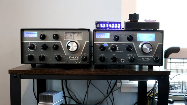
In the ham radio trade, gear such as the old Drake units [Dr. Scott M. Baker] has in his radio shack are often referred to as “boat anchors.” It refers to big, heavy radios that were perhaps a bit overengineered compared to the state of the art at the time they were designed, and it’s actually a shame that the name has taken on something of a pejorative connotation, since some of this gear is rock solid half a century or more after it was built.
But older gear is often harder to use, at least compared to the newer radios with microcontrollers and more stable oscillators inside. To make his 1970s-era Drake “Twins” setup of separate but linked receiver and transmitter a little more fun to use, [Scott] came up with this neat Raspberry Pi-based DDS-VFO project to keep his boat anchors afloat. Compared to the original mechanically tuned variable frequency oscillator in the Drake receiver, the direct-digital synthesis method promises more stability, meaning less knob-nudging to stay on frequency.
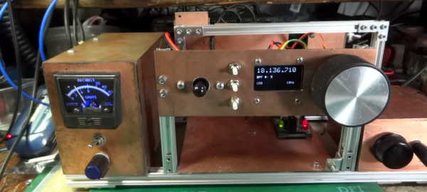
The hardware used for the DDS-VFO is actually pretty simple — just a Raspberry Pi Zero W driving an AD9850-based signal-generator module. Sending the signal to the Twins was another matter. That was done by tapping into the injection cable linking both units, which meant a few circuit complications to deal with signal attenuation. [Scott] also added amenities like a digital frequency display, optical encoder with crank-style knob to change frequency, and a host of Cherry MX keyswitches for quick access to different features.
From the look of the video below, the Twins are now rock-solid and a lot easier to use. This project is loosely based on a recent panadapter project [Scott] undertook for the receiver side of the Twins.
Continue reading “Boat Anchor Twins Get A Little Digital Help Staying On Frequency”
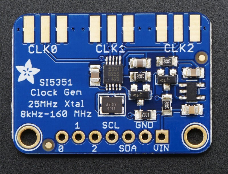 [Tom] used a Teensy 3.1 Arduino compatible board, to control the Si5351


