Take A Deep Dive Into A Commodity Automotive Radar Chip

When the automobile industry really began to take off in the 1930s, radar was barely in its infancy, and there was no reason to think something that complicated would ever make its way into the typical car. Yet here we stand less than 100 years later, and radar has been perfected and streamlined so much that an entire radar set can be built on a single chip, and commodity radar modules can be sprinkled all around the average vehicle.

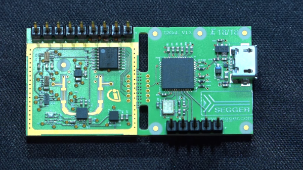
Looking inside these modules is always fascinating, especially when your tour guide is [Shahriar Shahramian] of The Signal Path, as it is for this deep dive into an Infineon 24-GHz automotive radar module. The interesting bit here is the BGT24LTR11 Doppler radar ASIC that Infineon uses in the module, because, well, there’s really not much else on the board. The degree of integration is astonishing here, and [Shahriar]’s walk-through of the datasheet is excellent, as always.

Things get interesting once he gets the module under the microscope and into the X-ray machine, but really interesting once the RF ASIC is uncapped, at the 15:18 mark. The die shots of the silicon germanium chip are impressively clear, and the analysis of all the main circuit blocks — voltage-controlled oscillator, power amps, mixer,  LNAs — is clear and understandable. For our money, though, the best part is the look at the VCO circuit, which appears to use a bank of fuses to tune the tank inductor and keep the radar within a tight 250-Mz bandwidth, for regulatory reasons. We’d love to know more about the process used in the factory to do that bit.

This isn’t [Shahriar]’s first foray into automotive radar, of course — he looked at a 77-GHz FMCW car radar a while back. That one was bizarrely complicated, though, so there’s something more approachable about a commodity product like this.

Continue reading “Take A Deep Dive Into A Commodity Automotive Radar Chip”

Remoticon Video: Intro To Modern Synthesis Using VCV Rack

Modular synthesizers, with their profusion of knobs and switches and their seemingly insatiable appetite for patch cables, are wonderful examples of over-complexity — the best kind of complexity, in our view. Play with a synthesizer long enough and you start thinking that any kind of sound is possible, limited only by your imagination in hooking up the various oscillators, filters, and envelope generators. And the aforementioned patch cables, of course, which are always in short supply.

Luckily, though, patch cables and the modules they connect can be virtualized, and in his 2020 Remoticon workshop, Jonathan Foote showed us all the ways VCV Rack can emulate modular synthesizers right on your computer’s desktop. The workshop focused on VCV Rack, where Eurorack-style synthesizer modules are graphically presented in a configurable rack and patched together just like physical synth modules would be.

Continue reading “Remoticon Video: Intro To Modern Synthesis Using VCV Rack”

Teardown: Mini GPS Jammer

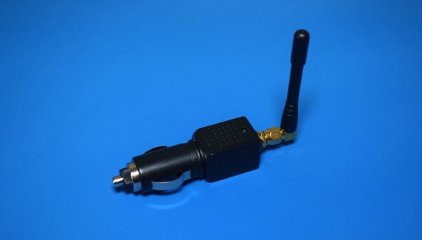
If you spend enough time trolling eBay for interesting electronic devices to take apart, you’re bound to start seeing suggestions for some questionable gadgets. Which is how I recently became aware of these tiny GPS jammers that plug directly into an automotive 12 V outlet. Shipped to your door for under $10 USD, it seemed like a perfect device to rip open in the name of science.

Now, you might be wondering what legitimate uses such a device might have. Well, as far as I’m aware, there aren’t any. The only reason you’d want to jam GPS signals in and around a vehicle is if you’re trying to get away with something you shouldn’t be doing. Maybe you’re out driving a tracked company car and want to enjoy a quick two hour nap in a parking lot, or perhaps you’re looking to disable the integrated GPS on the car you just stole long enough for you to take it to the chop shop. You know, as one does.

But we won’t dwell on the potentially nefarious reasons that this device exists. Hackers have never been too choosy about the devices they investigate and experiment with, and there’s no reason we should start now. Instead, let’s take this piece of gray-area hardware for a test drive and see what makes it tick.

Continue reading “Teardown: Mini GPS Jammer”

An Arduino As A PLL

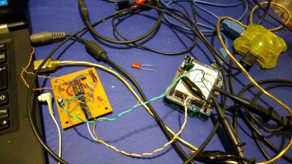
At the heart of many amateur radio and other projects lies the VFO, or Variable Frequency Oscillator. Decades ago this would have been a free-running LC tuned circuit, then as technology advanced it was replaced by a digital phase-locked-loop frequency synthesiser and most recently a DDS, or Direct Digital Synthesis chip in which the waveform is produced directly by a DAC. The phase-locked loop (PLL) remains a popular choice due to ICs such as the Si5351 but is rarely constructed from individual chips as it once might have been. [fvfilippetti] has revisited this classic circuit by replacing some of its complexity with an Arduino (Spanish language, Google Translate link).

The internals of a PLL frequency synthesiser
The internals of a PLL frequency synthesiser. Image by Chetvorno – CC0

A PLL is a simple circuit in which one oscillator is locked to another by controlling it with a voltage derived from comparing the phase of the two. Combining a PLL with a set of frequency dividers creates a frequency synthesiser, in which a variable frequency oscillator can be locked to a single frequency crystal with the output frequency set by the division ratios. The classic PLL chip is the CMOS 4046 which would have been combined with a pile of logic chips to make a frequency synthesiser. The Arduino version uses the Arduino’s internal peripherals to take the place of crystal oscillator, dividers, and phase comparator, resulting in an extremely simple physical circuit of little more than an Arduino and a VCO for the 40 metre amateur band. The code can be found on GitLab, should you wish to try for yourself.

It would be interesting to see how good this synthesiser is at maintaining both a steady frequency and minimal phase noise. It’s tempting to think of such things as frequency synthesisers as a done deal, so it’s always welcome to see somebody bringing something new to them. Meanwhile if PLLs are new to you, we have just the introduction for you.

Fail Of The Week: How Not To Design An RF Signal Generator

We usually reserve the honor of Fail of the Week for one of us – someone laboring at the bench who just couldn’t get it together, or perhaps someone who came perilously close to winning a Darwin Award. We generally don’t highlight commercial products in FotW, but in the case of this substandard RF signal generator, we’ll make an exception.

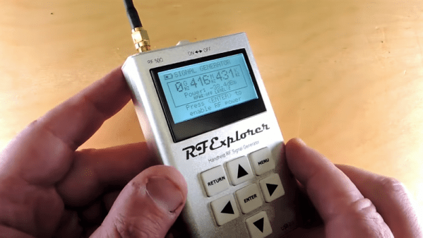
We suppose the fail-badge could be pinned on [electronupdate] for this one in a way; after all, he did shell out $200 for the RF Explorer signal generator, which touts coverage from 24 MHz to 6 GHz. But in true lemons-to-lemonade fashion, the video below he provides us with a thorough analysis of the unit’s performance and a teardown of the unit.

The first step is a look at the signal with a spectrum analyzer, which was not encouraging. Were the unit generating a pure sine wave as it should, we wouldn’t see the forest of spikes indicating harmonics across the band. The oscilloscope isn’t much better; the waveform is closer to a square wave than a sine. Under the hood, he found a PIC microcontroller and a MAX2870 frequency synthesizer, but a conspicuous absence of any RF filtering components, which explains how the output got so crusty. Granted, $200 is not a lot to spend compared to what a lab-grade signal generator with such a wide frequency range would cost. And sure, external filters could help. But for $200, it seems reasonable to expect at least some filtering.

We applaud [electronupdate] for taking one for the team here and providing some valuable tips on RF design dos and don’ts. We’re used to seeing him do teardowns of components, like this peek inside surface-mount inductors, but we like thoughtful reviews like this too.

Continue reading “Fail Of The Week: How Not To Design An RF Signal Generator”

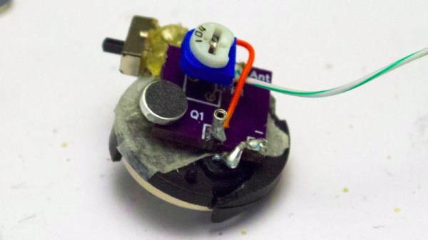
An Especially Tiny And Perfectly Formed FM Bug

It used to be something of an electronic rite of passage, the construction of an FM bug. Many of us will have taken a single RF transistor and a tiny coil of stiff wire, and with the help of a few passive components made an oscillator somewhere in the FM broadcast band. Connect up a microphone and you were a broadcaster, a prankster, and probably set upon a course towards a life in electronics. Back in the day such a bug might have been made from components robbed from a piece of scrap consumer gear such as a TV or VCR, and perhaps constructed spider-web style on a bit of tinplate. It wouldn’t have been stable and it certainly wouldn’t have been legal in many countries but the sense of achievement was huge.

As you might expect with a few decades of technological advancement, the science of FM bugs has moved with the times. Though you can still buy the single transistor bugs as kits there is a whole range of fancy chips designed for MP3 players that provide stable miniature transmitters with useful features such as stereo encoders. That’s not to say there isn’t scope for an updated simple bug too though, and here [James] delivers the goods with his tiny FM transmitter.

Gone is the transistor, and in its place is a MAX2606 voltage-controlled oscillator. The on-chip varicap and buffer provided by this device alleviate some of the stability issues suffered by the transistor circuits, and to improve performance further he’s added an AP2210 low-dropout regulator to catch any power-related drift. If it were ours we’d put in some kind of output network to use both sides of the differential output, but his single-ended solution at least offers simplicity. The whole is put on a board so tiny as to be dwarfed by a CR2032 cell, and we can see that a bug that size could provide hours of fun.

This may be a small and simple project, but it has found its way here for being an extremely well-executed one. It’s by no means the first FM bug we’ve shown you here, just a few are this one using scavenged SMD cellphone parts, or this more traditional circuit built on a piece of stripboard.

3D Printing A Synthesizer

Before there were samplers, romplers, Skrillex, FM synths, and all the other sounds that don’t fit into the trailer for the new Blade Runner movie, electronic music was simple. Voltage controlled oscillators, voltage controlled filters, and CV keyboards ruled the roost. We’ve gone over a lot of voltage controlled synths, but [Tommy] took it to the next level. He designed a small, minimum viable synth based around the VCO in an old 4046 PLL chip

For anyone who remembers [Elliot]’s Logic Noise series here on Hackaday, this type of circuit should be very familiar. The only thing in this synth is a few buttons, a variable resistor for each button, and the very popular VCO for an analog square wave synth.

The circuit for this synth is built in two halves. The biggest, and what probably took the most time designing, is the key bed. This is a one-octave keyboard that’s completely 3D printed. We’ve seen something like this before in one of the projects from the SupplyFrame Design Lab residents, though while that keyboard worked it was necessary for [Tim], the creator of that project, to find a company that could make custom key beds for him.

The rest of the circuit is just a piece of perf board and the 4046. This project is all wrapped up in a beautiful all-wood enclosure with 3D printed hinges, knobs, and a speaker grille. The sound is phenomenal, and exactly what you want from a tiny monophonic square wave synth. You can check out a video of that below.

Continue reading “3D Printing A Synthesizer”