Hidden TV-Out On The Nintendo DS Lite

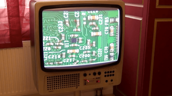
The DS Lite was one of Nintendo’s most popular handheld gaming consoles, but unbeknownst to all, it has a hidden feature that could have made it even more popular. Digging through the hardware and firmware, the [Lost Nintendo History] team discovered the System-on-Chip (SoC) in the DS Lite can output a composite video signal.

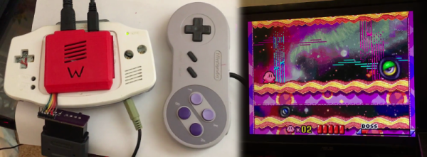
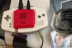
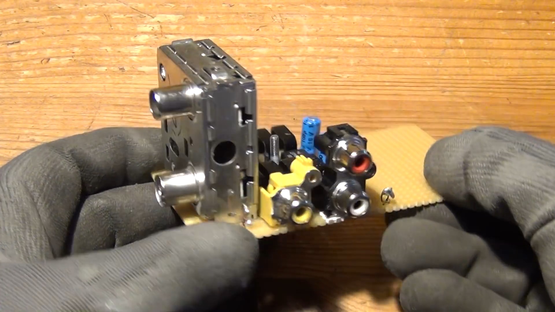
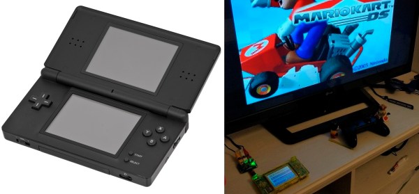
The SoC can output a 10-bit digital output running at 16.7 MHz, but it is disabled by the stock firmware early in the boot process, so custom firmware was required. It still needs to be converted to an analog signal, so a small adaptor board with a DAC (digital-analog converter) and op-amp is attached to the flex cable of the upper screen. A set of buttons on the board allow you to select which screen is displayed on the TV. The adaptor board is open source, and the Gerbers and schematics are available on GitHub.

The current version of the adaptor board disables the upper screen, but the [Lost Nintendo History] team is considering designing a pass-through board to eliminate this disadvantage. The TV-out mod can also be combined with the popular Macro mod, in which the upper screen is removed to turn it into a Game Boy Advance. The Nintendo DS is a popular hacking subject, and we’ve been covering them for well over a decade.

HDMI Out On The Gameboy Advance

The Gameboy line of handheld systems from Nintendo have been wildly popular, but lack one major thing – a video output. This can be troublesome if you’d like to view the games on a bigger screen, for more comfortable gaming sessions or detail work like producing chiptunes. One option is to use the Gameboy Player for the Gamecube, however that system’s age means you’re out of luck if you want a crisp, clear picture on a modern digital display. Wouldn’t it be great if you could get HDMI output from a Gameboy Advance Instead?

A family resemblance?

When it comes to working with video signals, FPGAs can’t be beat. [Stephen] leverages an FPGA in this project to read the GBA’s video signals and convert them to the modern digital format. Unfortunately, it’s not a seamless install – limited space means the GBA’s screen must be entirely removed, replaced with the adapter in a manner resembling the terrifying Facehugger.

Packaging aside, the output from the device is nothing short of stunning – the graphics are absolutely crystal clear when displayed on a modern HDMI television. This is because the FPGA is capturing the exact digital output from the GBA, and piping it out as HDMI – there’s no analog fuzziness, conversions or noise to spoil the image. Output is a tasty 1280×720, upscaled from the GBA’s original resolution. For more details, check out the forum thread where [Stephen] runs through the build.

The only thing missing  is details – we’d love to know more about the exact hardware used, and any trials and tribulations during the build! As far as we can tell, the build doesn’t stop at just video – a SNES controller is used instead of the original buttons, and we have a feeling sound is being passed over the HDMI channel as well sound is piped to the TV from the GBA’s headphone port.

It’s great to see these projects for old hardware come out – modern hardware has the muscle to achieve things previously unthinkable on retro consoles. We’ve seen similar projects before – like adding VGA to an original Game Boy.

Continue reading “HDMI Out On The Gameboy Advance”

Send A Raspberry Pi Back In Time To 1980

One of our favorite hacker-scavengers on YouTube, [The Post-Apocalyptic Inventor], has been connecting his Raspberry Pi up to nearly every display that he’s got in his well-stocked junk pile. (Video embedded below.)

Modern monitors with an HDMI input connect right up to the Pi. Before HDMI came VGA, but the Pi doesn’t do that natively. One solution is to use a composite-to-VGA converter and pull the composite signal out of the audio jack. Lacking the right 4-pole audio cable, [TPAI] soldered some RCA plugs directly onto the Pi, and plugged that into the converter. On a yet-older monitor, he faced a SCART adapter. If you’re European, you’ll know these — it’s just composite video with a different connector. Good thing he had a composite video signal already on hand.

online-with-my-1980-tv-set-huc2ls56hwimkv-shot0004The pièce de resistance, though, was attaching the Pi to his 1980 Vega TV set. It only had an antenna-in connector, so he needed an RF modulator. With a (presumably) infinite supply of junk VCRs on hand, he pulled an upconverter out of the pile, and got the Pi working with the snazzy retro TV.

Continue reading “Send A Raspberry Pi Back In Time To 1980”

Going A Long Way For Game Boy Advanced Video Out

Here’s an intense hack that lets [Matt Evans] play Game Boy Advanced on a larger LCD monitor. He didn’t take the easy way out during any step of the process.

He’s using an FPGA to translate the LCD signals from the GBA hardware into a 1280×960 picture that is then pushed to the large monitor. But did he use an FPGA development board? No, instead he picked up an old PCI card at a surplus store because it had a Xilinx Virtex-E FPGA. So the first thing he had to do there was to remove unneeded components and figure out how to make the connections to reprogram that chip.

So next you’d grab a working monitor and hook it up to the FPGA signal, right? Wrong, [Matt] had a slightly borked monitor, getting rid of the LVDS section and wiring up his own connections to push the RGB signals through in parallel.

Yeah, that’s a lot of work. But as you can see in the clip after the break, it works like a charm. If you’re looking for some other gnarly video-out hacks, check out this one that lets you play Game Boy on an oscilloscope.

Continue reading “Going A Long Way For Game Boy Advanced Video Out”

Simple VGA Interface For Tiny FPGA Boards

fpga_vga_adapter

[devb] has been playing around with XESS FPGA boards for ages, and as long as he can remember, they have had built-in VGA interfaces. His newest acquisition, a XuLA FPGA board, doesn’t have any external parts or ports aside from a USB connector. He needed to get video output from the board, so he decided to build a VGA interface himself.

He prototyped a 512-color VGA interface board which worked just fine, but he thought it would be way too cumbersome to use for each and every project. To keep life simple, he designed a small PCB that integrates a VGA connector and all of the resistors he needed to get the signal from the FPGA. His boards plug directly into a breadboard, so only a handful of wires is needed to connect the FPGA to a monitor.

As you can see on his site, the adapter works quite well, allowing the FPGA to put out a crisp 800×600 image with little fuss. [devb] has also posted all of his design files on his site in Eagle format for anyone interested in replicating his work.