Understand Your Tools: Finger Exercises

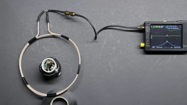
A dip meter is basically a coil of wire that, when you excite it, you can use to tell if something inside that coil is resonating along. This lets you measure unknown radio circuits to figure out their resonant frequency, for instance. This week, we featured a clever way to make a dip meter with a nanoVNA, which is an odd hack simply because a dip meter used to be a common spare-parts DIY device, while a vector network analyzer used to cost more than a house.

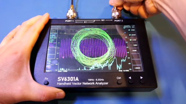
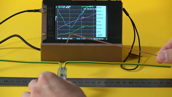
Times have changed, and for the better. Nowadays, any radio amateur can pick up a VNA for less than the cost of all but the cheesiest of walkie talkies, putting formerly exotic test equipment in the hands of untrained mortals. But what good is a fancy-pants tool if you don’t know how to use it? Our own Jenny List faced exactly this problem when she picked up a nanoVNA, and her first steps are worth following along with if you find yourself in her shoes.

All of this reminded me of an excellent series by Mike Szczys, “Scope Noob”, where he chronicled his forays into learning how to use an oscilloscope by running all of the basic functions by working through a bunch of test measurements that he already knew the answer to.

It strikes me that we could use something like this for nearly every piece of measuring equipment. Something more than just an instruction manual that walks you through what all the dials do. Something that takes you through a bunch of example projects and shows you how to use the tool in question through a handful of projects. Because these days, access to many formerly exotic pieces of measuring gear has enabled many folks to have gear they never would have had before – and all that’s missing is knowing how to drive them.

A NanoVNA As A Dip Meter

A staple of the radio amateur’s arsenal of test equipment in previous decades was the dip meter. This was a variable frequency oscillator whose coil would be placed near the circuit to be tested, and which would show an abrupt current dip on a moving coil meter when its frequency matched the resonant frequency of what it was testing. For some reason the extremely useful devices seem hard to come by in 2024, so [Rick’s Ham Shack] has come along with a guide to using a nanoVNA in their place.

It’s a simple enough technique, indeed it’s a basic part of using these instruments, with a large sensor coil connected to the output port and a frequency sweep set up on the VNA. The reactance graph then shows any resonant peaks it finds in the frequency range, something easily demonstrated in the video below the break by putting a 20 meter (14 MHz) trap in the coil and seeing an immediate clear peak.

For many readers this will not be news, but for those who’ve not used a VNA before it’s a quick and easy demo of an immediate use for these extremely versatile instruments. For those of us who received our callsigns long ago it’s nothing short of miraculous that a functional VNA can be picked up at such a reasonable price, and we’d go as far as to suggest that non radio amateurs might find one useful, too. Read our review, if you’re interested.

Continue reading “A NanoVNA As A Dip Meter”

Vector Network Analyzer Demo And Teardown

[Kerry Wong], ever interested in trying out and tearing down electrical devices, demonstrates and examines the SV 6301a Handheld Vector Network Analyzer. He puts the machine through its paces, noting that the 7 inch touchscreen is a pretty nice feature for those whose eyesight isn’t quite what it used to be.

The internals are similar to the nanoVNA-F V3, but not identical.

What’s a Vector Network Analyzer (VNA)? It’s not for testing Ethernet or WiFi. It’s aimed at a more classical type of “network”. The VNA tests and evaluates characteristics of electrical networks, especially as related to RF and microwave.

It provides detailed information about properties across a specified frequency range, making it an indispensable tool for advanced work. Tektronix has a resource page that goes into detail about exactly what kinds of things a VNA is good for.

[Kerry] shows off a few different features and sample tests before pulling the unit apart. In the end, he’s satisfied with the features and performance of the device, especially the large screen and sensible user interface.

After all, not every piece of test equipment does a great job at fulfilling its primary function, like the cheap oscilloscope that was a perhaps a little too cheap.

Continue reading “Vector Network Analyzer Demo And Teardown”

The Dipole Antenna Isn’t As Simple As It Appears

Dipole antennas are easy, right? Just follow the formula, cut two pieces of wire, attach your feedline, and you’re on the air.  But then again, maybe not. You’re always advised to cut the legs a little long so you can trim to the right length, but why? Shouldn’t the math just be right? And what difference does wire choice make on the antenna’s characteristics? The simple dipole isn’t really that simple at all.

If you’ve got antenna questions, check out [FesZ]’s new video on resonant dipoles, which is a deep dive into some of the mysteries of the humble dipole. In true [FesZ] fashion, he starts with simulations of various dipole configurations ranging from the ideal case — a lossless conductor in free space with as close to zero diameter conductors as the MMANA antenna simulator can support — and gradually build up to more practical designs. Continue reading “The Dipole Antenna Isn’t As Simple As It Appears”

NFC Performance: It’s All In The Antenna

NFC tags are a frequent target for experimentation, whether simply by using an app on a mobile phone to interrogate or write to tags, by incorporating them in projects by means of an off-the-shelf module, or by designing a project using them from scratch. Yet they’re not always easy to get right, and can often give disappointing results. This article will attempt to demystify what is probably the most likely avenue for an NFC project to have poor performance, the pickup coil antenna in the reader itself.

A selection of the NFC tags on my desk

The tags contain chips that are energised through the RF field that provides enough power for them to start up, at which point they can communicate with a host computer for whatever their purpose is.

“NFC” stands for “Near Field Communication”, in which data can be exchanged between physically proximate devices without their being physically connected.  Both reader and tag achieve this through an antenna, which takes the form of a flat coil and a capacitor that together make a resonant tuned circuit. The reader sends out pulses of RF which is maintained once an answer is received from a card, and thus communication can be established until the card is out of the reader’s range. Continue reading “NFC Performance: It’s All In The Antenna”

Calibrating A VNA The Proper Way

Those of us who have bought cheap TinyVNA devices for our RF experimentation will be used to the calibration procedure involving short-circuit, 50 Ω, and open terminations, followed by a direct connection between ports. We do this with a kit of parts supplied with the device, and it makes it ready for our measurements. What we may not fully appreciate at the level of owning such a basic instrument though, is that the calibration process for much higher-quality instruments requires parts made to a much higher specification than the cheap ones from our TinyVNA. Building a set of these high-quality parts is a path that [James Wilson] has taken, and in doing so he presents a fascinating discussion of VNA calibration and the construction of standard RF transmission line components.

We particularly like the way that after constructing his short, load and open circuit terminations using high-quality SMA sockets, he put a custom brass fitting 3D printed by Shapeways on the end of each to make them easier to handle while preserving their RF integrity. If we’d bought a set of terminations looking like these ones as commercial products we would be happy with their quality, but the real test lay in their performance. Thanks to a friend he was able to get them tested on instruments with much heftier price tags, and found them to be not far short of the simulation and certainly acceptable within his 3 GHz range.

Curious about VNAs at the affordable end of the spectrum? We took a look at the TinyVNA, which while it is something of a toy is still good enough for lower frequency measurements.

LibreVNA Is A Quality Open Hardware Vector Network Analyser

There was a time when a Vector Network Analyser or VNA was the type of instrument that cost as much as a very fancy car or even a small house. The advent of commodity semiconductors that perform at high RF frequencies coupled with microcontrollers powerful enough to handle the data acquisition and processing might not yet have put those high-perfomance instruments within reach, but at our end of the market it’s opened the possibilities for some useful yet affordable devices. A fresh contender comes from [Jankae], whose LibreVNA tops out at 6 GHz and shows some significant attention to design detail that puts it above some of the budget offerings.

At its heart is the versatile Si5351 multi-way clock generator, accompanied by a pair of MAX2871 phase-locked-loop chips for the higher frequency local oscillators. A switched bank of low-pass filters take care of local oscillator harmonics, and in the receive chain there are ADL5081 mixers feeding a dual conversion IF running at 70 MHz and then 300 kHz. Finally the ADCs are Microchip’s MCP3313, and all is kept in sync by an FPGA and an STM32G431 microcontroller. The main data proccessing is offloaded to a host computer, with a software package and GUI able to be compiled on Windows, Linux, and OSX.

The PCB shows the attention to detail, not least in the power supply arrangements, with every major component receiving its own regulator to ensure no RF makes it down the power rails. It’s clear that a properly made LibreVNA won’t be as cheap as some of its rivals, but we think the corresponding performance hike would make the extra cost worthwhile.

If VNAs are new to you, we covered an introduction from [W2AEW] a while back.