Logic Noise: Digital To Analog With An R-2R DAC

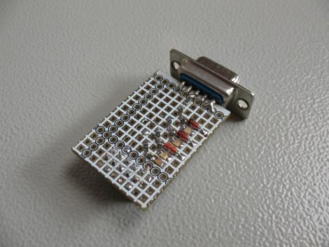
Making sound with digital logic usually calls for a Digital to Analog converter. Building one can be very simple, and the sound quality out of an R-2R Ladder is actually pretty good.

In the last edition of Logic Noise, we built up a (relatively) simple VCO — voltage-controlled oscillator — that had roughly one-volt-per-octave response. I even demonstrated it working mostly in tune with another synth’s keyboard. But what if you don’t have a control-voltage keyboard sitting around or you want to combine all of the logic-based circuits that we’ve been building with other circuits under voltage control? That’s where the digital to analog (DAC) voltage converter comes in.

Continue reading “Logic Noise: Digital To Analog With An R-2R DAC”

MacGyver, Jedi Knights, Ammo Stockpiles, And Candy Crush

Everyone’s favorite machinist, tinkerer, YouTube celebrity, deadpan comedian, and Canadian is back with a tale of popping a few benzos, stumbling around Mexico, and wondering why everyone else on the planet is so stupid.

The hero of our story considered the feasibility of one hundred and eighty-sixth trimester abortions as he stood outside a Mexican airport watching a stockbroker complain about the battery in his cellphone. Meanwhile, cars drove by.

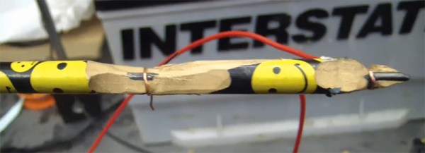
Here’s how you charge a phone with a car battery and an ‘ol Dixon Ticonderoga.

To charge a battery, all you really need to do is connect the terminals to a power source with the right voltage. A cell phone battery needs about three volts, and a car battery has twelve. You need a voltage divider. You can get that with a pencil. Take out a knife, get to the carbon and clay wrapped in wood, and wire the battery up. Make a cut a quarter of the way down this rather long resistor, and there you will find something around three volts.

Does it work? Yeah. It works even better if you have some tape to hold wires onto the cell phone battery when charging. Is it smart? It is if there is no other conceivable way of charging your cell phone. Should you do it? Nah. Video below. Thanks [Morris] for the link.

Continue reading “MacGyver, Jedi Knights, Ammo Stockpiles, And Candy Crush”

Giant Resistor-shaped Ohmmeter

resistance-measuring-resistor

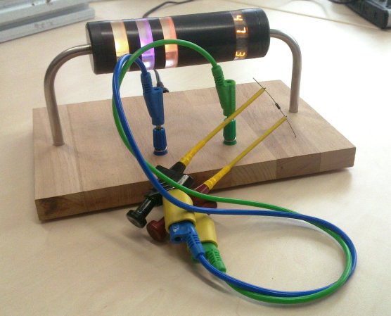
The fun of having a giant resistor-shaped Ohmmeter is that it reads back the resistance by displaying the color code. If you’re not too hot with decoding those bands there’s a helper band to the right which will display the value numerically.

All of the electronics are housed in the opaque part of the resistor, making for a nice low-profile base. The bent leads are hollow and allow [Sebastian] and his friend to run power and measurement leads through to the power connector on the back and the pair of banana jacks near the front. Each translucent ring houses an RGB LED, except for the one on the right which has four 7-segment display modules embedded in it. An ATmega168 takes the measurements using its Analog to Digital Converter (ADC) to read the value from a voltage divider. You can see a quick demo of the Ohmmeter in the video after the jump.

This would be a fun thing to pair with that giant breadboard.

Continue reading “Giant Resistor-shaped Ohmmeter”

Adding Charging Back To Old Apple Accessories

From time-to-time we’ve been frustrated by the lack of backwards compatibility for Apple accessories. We have a great Monster FM transmitter that used the screen of the original iPod to select a channel. That was a feature we just loved which it never worked with any future hardware. We may not be able to get that back, but perhaps this hack can help us implement the ability to charge newer Apple devices using older accessories.

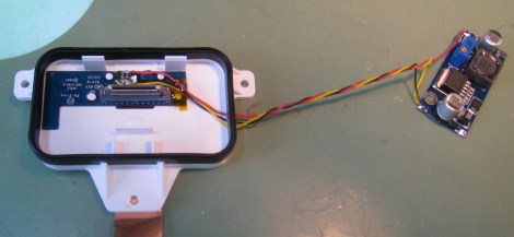
Seen above is the mounting dock from the iPod Hi-Fi speakers released back in 2006. Apparently the sound out of this set of speakers is just great, but you won’t be able to charge your modern device while it’s playing music. That is unless you’re not afraid to solder on a few simple components and roll in a switching regulator which can source at least one Amp of current. As we’ve seen in the past, Apple uses a couple of voltage dividers to identify modern chargers. These are installed on the D+ and D- lines of the USB connector and are pretty easy to recreate if you know the voltage levels the device is looking for. In this case a 39K, two 51k, and one 75k surface mount resistors are free-formed right next to the connector on the Hi-Fi’s dock PCB. The regulator on the right supplies the juice for charging. It’ll charge modern devices now, and even work with the iPhone five if you use a simple dock connector adapter.

Raspberry Pi As A PIC Programmer

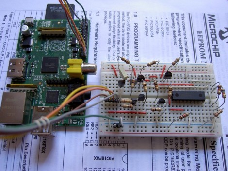
[Giorgio Vazzana] turned his Raspberry Pi into a PIC programmer using a rather small collection of common parts. It supports about a dozen different chips from the 16F family. But we’d guess that software is the limiting factor when it comes to supporting more chips.

Generally the problem with PIC programming is the need for a 12V supply. He chose to use an external 12V supply and a 78L05 linear regulator to derive the 5V rails from it. With the power worked out there are some level conversion issues to account for. The RPi provides 3.3V on the GPIO header pins, but 5V logic levels are needed for programming. He built transistor and voltage divider circuits to act as level converters. The programming software bit bangs the pins with a write time of less than eight seconds per 1k words of program data. So far this does not work with ICSP, but he plans to add that feature in a future version.

Serial Port JTAG Programmer

If you’re planning to do some hacking with CPLD or FPGA chips you’ll need a way to program them. JTAG is one of the options and here’s a cheap method that uses the serial port (translated).

This method requires only four signals (TDI, TMS, TCK and TDO) plus ground. But the problem is that an RS232 serial port operates with 12V logic levels and the JTAG side of the programmer needs to operate with the logic levels native to the device you’re programming. Commercial programmers use a level convert IC to take care of this for you, but that doesn’t mesh with the cheap goal of this project. Instead, [Nicholas] uses Zener diodes and voltage dividers to make the conversion. There is also an LED for each data signal to give some feedback if you’re having trouble.

You can use this along with a programming application that [Nicholas] whipped up using Visual Studio. It works well via the serial port, but he did try programming with a USB-to-Serial dongle. He found that this method slows the process down to an unbearable 5-minutes. Take a look, maybe you can help to get that sloth-like programming up to a manageable speed.

[Thanks Alex]

Light Sensitive MIDI Glove

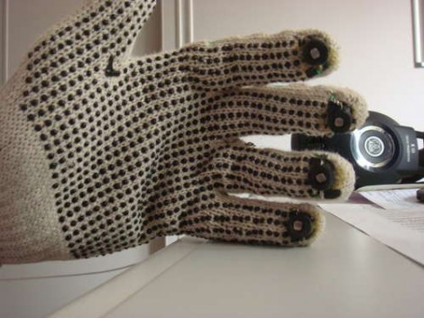
The latest offering in glove-based noisemakers forsakes commonly used flex sensors in favor or photoresistors. [Bruno Ratnieks] is responsible for this musical glove and his methods will be very easy to recreate. He used an Arduino to interface with it while providing a USB connection to your audio software. The sensors themselves couldn’t be easier to throw together, with each photoresistor creating a voltage divider when combined with a fixed-value resistor. That’s all the hardware you need, and with some creative coding you can making it do much more than the effects heard in the video after the break.

Some will say that [Bruno] simply didn’t used enough duct tape with his project design. Be we liked how he wove the wiring into the mesh of these knit gloves to keep it firmly in place.

Continue reading “Light Sensitive MIDI Glove”