Wien Bridge Oscillator Drives Distortion Into The Floor

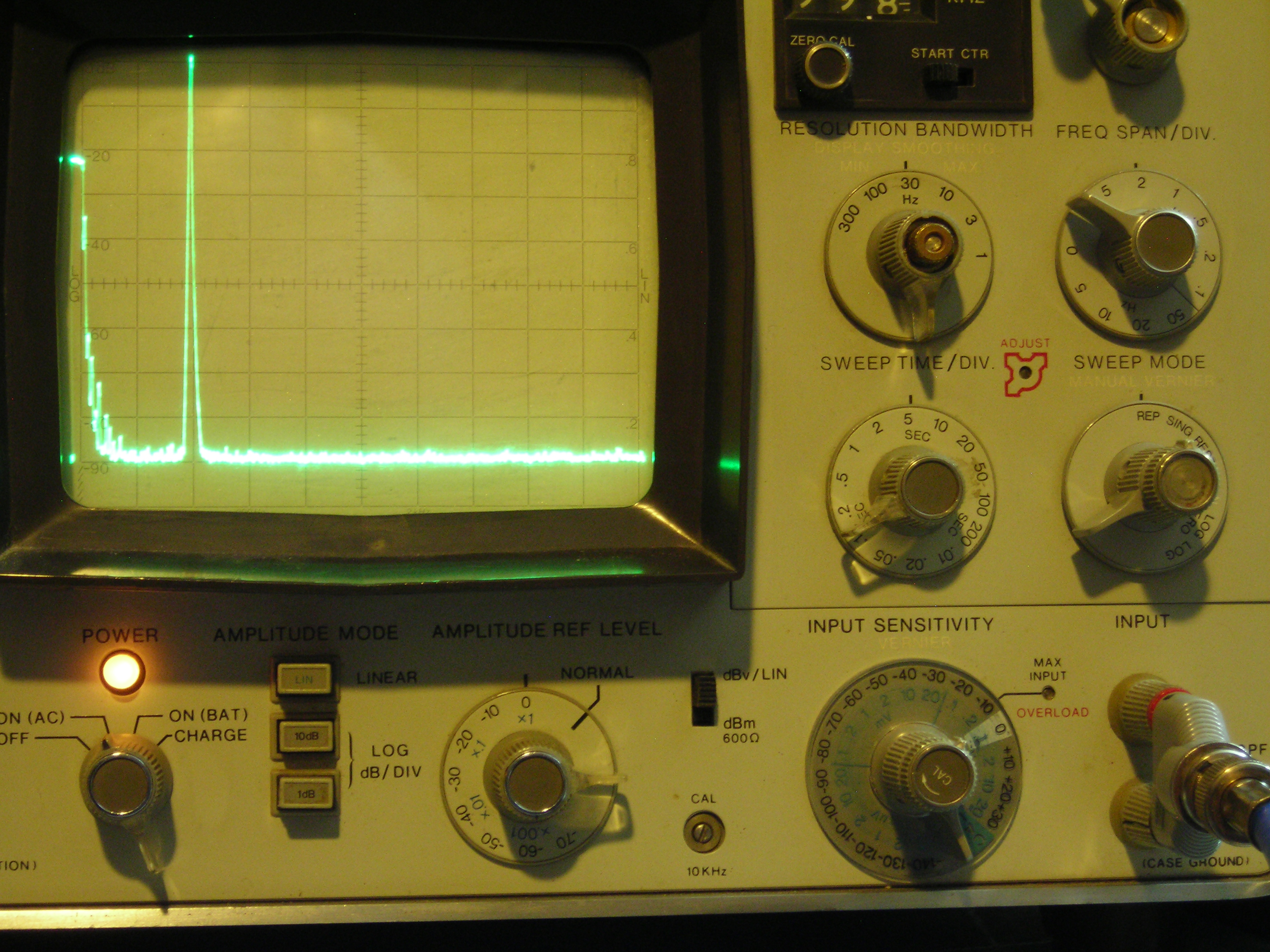
It’s not often that a single photo can tell you pretty much everything you need to know about a project, but the spectrum analyzer screenshot nearby is the perfect summary of this over-the-top low-distortion audio oscillator build. But that doesn’t mean there’s not a ton of interesting stuff going on with this one, so buckle up.

One spike at the fundamental and not much more.

The project is by [Basin Street Design], who doesn’t really offer much by way of inspiration for this undertaking, nor a discussion on what this will be used for. But the design goals are pretty clear: build an oscillator with as little distortion as possible across the audio frequency range.

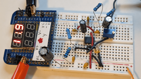
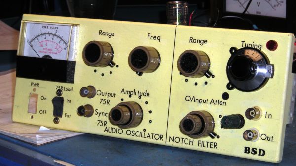
The basic circuit is the well-known Wien bridge oscillator where the R-C pairs are switched in and out of the feedback loop to achieve frequency range control. This was accomplished with rotary switches rebuilt from their original configuration in a Heathkit IG-18 sine/square wave generator, a defunct instrument that was gutted and used as an enclosure for this build. There are a lot of other treats here, too, like the automatic gain control (AGC) that uses a homebrew voltage-controlled resistor made from an incandescent lamp and a cadmium sulfide photoresistor glued inside a piece of brake line, and an output attenuator made from discrete resistors that drops the output in 10 dB steps while maintaining an overall 75-Ohm impedance.

But at the end of the day, it all comes down to that single spike on the spectrum analyzer, with no apparent harmonics. To make sure there wasn’t something hiding down in the noise, [Basin Street] added a notch filter to lower the fundamental by 60 dB, allowing the spectrum analyzer sensitivity to be cranked way up. Harmonics were visible, but so far down into the noise — as low as -115 dBc — that it’s hardly worth mentioning.

There’s a lot more detail in this one, so dive in and enjoy. If you want another take on Wien bridge circuits, check out this recent LM386-based oscillator. Just don’t expect such low distortion with that one.

An LM386 Oscillator Thanks To Tungsten Under Glass

Once ubiquitous, the incandescent light bulb has become something of a lucerna non grata lately. Banned from home lighting, long gone from flashlights, and laughed out of existence by automotive engineers, you have to go a long way these days to find something that still uses a tungsten filament.

Strangely enough, this lamp-stabilized LM386 Wien bridge oscillator is one place where an incandescent bulb makes an appearance. The Wien bridge itself goes back to the 1890s when it was developed for impedance measurements, and its use in the feedback circuits of vacuum tube oscillators dates back to the 1930s. The incandescent bulb is used in the negative feedback path as an automatic gain control; the tungsten filament’s initial low resistance makes for high gain to kick off oscillation, after which it heats up and lowers the resistance to stabilize the oscillation.

For [Grug Huler], this was one of those “just for funsies” projects stemming from a data sheet example circuit showing a bulb-stabilized LM386 audio oscillator. He actually found it difficult to source the specified lamp — there’s that anti-tungsten bias again — but still managed to cobble together a working audio oscillator. The first pass actually came in pretty close to spec — 1.18 kHz compared to the predicted 1.07 kHz — and the scope showed a very nice-looking sine wave. We were honestly a bit surprised that the FFT analysis showed as many harmonics as it did, but all things considered, the oscillator performed pretty well, especially after a little more tweaking. And no, the light bulb never actually lights up.

Thanks to [Grug] for going down this particular rabbit hole and sharing what he learned. We love builds like this that unearth seemingly obsolete circuits and bring them back to life with modern components. OK, calling the LM386 a modern component might be stretching things a bit, but it is [Elliot]’s favorite chip for a reason.

Continue reading “An LM386 Oscillator Thanks To Tungsten Under Glass”

Circuit VR: Oscillating Bridges

Circuit VR is where we talk about a circuit and examine how it works in simulation with LT Spice. This time we are looking at a common low-frequency oscillator known as the Wien bridge oscillator.

What makes an oscillator oscillate? A circuit with amplification that gets the same amount of the output signal fed back into its input, in phase, will oscillate. This is the Barkhausen criterion. Here, we’re going to look into what makes an oscillator work in simulation, and gain some insight into what happens when there’s too much feedback and too little.

In particular, we’ll look at the Wien bridge oscillator, a very simple design that originated as a way to measure impedance back in 1891. Modern versions add some additional features, but let’s start with the most simple implementation and work our way up.

Continue reading “Circuit VR: Oscillating Bridges”

Model Sputnik Finds Its Voice After Decades Of Silence

As we approach the 60th anniversary of the human race becoming a spacefaring species, Sputnik nostalgia will no doubt be on the rise. And rightly so — even though Sputnik was remarkably primitive compared to today’s satellites, its 1957 launch was an inflection point in history and a huge achievement for humanity.

The Soviets, understandably proud of their accomplishment, created a series of commemorative models of Earth’s first artificial moon as gifts to other countries. How one came into possession of the Royal Society isn’t clear, but [Fran Blanche] found out about it through a circuitous route detailed in the video below, and undertook to reproduce the original electronics from the model that made the distinctive Sputnik beeps.

The Royal Society’s version of the model no longer works, but luckily it came with a schematic of the solid-state circuit used to emulate the original’s vacuum-tube guts. Intent on building the circuit as close to vintage as possible and armed with a bag of germanium transistors from the 60s, [Fran] worked through the schematic, correcting a few issues here and there, and eventually brought the voice of Sputnik back to life.

If you think we’ve covered Sputnik’s rebirth before, you may be thinking about our article on how some hams rebuilt Sputnik’s guts from a recently uncovered Soviet-era schematic. [Fran]’s project just reproduces the sound of Sputnik — no license required!

Continue reading “Model Sputnik Finds Its Voice After Decades Of Silence”

[Jeri] Uses Light Bulbs In An Oscillator

Way back when [Ms Ellsworth] was a kid, she kept seeing the same circuit over and over again in her various op-amp books. It was a Wien bridge oscillator, a small circuit that outputs a sine wave with the help of a light bulb. Now that [Jeri] is much wiser, she decided to play around with this strange oscillator and found it’s actually pretty impressive for, you know, a light bulb.

The interesting portion of the Wien bridge is the gain portion of the circuit. It’s just a simple resistor divider, with a light bulb thrown in on one of its legs. When the current increases, this causes the light bulb to warm up (not enough to glow, though). When the temperature increases, the resistance in the light bulb increases, making the oscillator reach an equilibrium.

It’s a clever setup, but what about swapping out a resistor in place of the light bulb? In the video, [Jeri] tries just that, and it’s a mess. Where the light bulb circuit is amazingly stable with very, very low distortion, the resistor circuit looks like a disaster on the scope with harmonics everywhere.

A very cool build that would be perfect for an audio synth, but as [Jeri] says in her YouTube comments, “This doesn’t have enough distortion for indie bands.”

Continue reading “[Jeri] Uses Light Bulbs In An Oscillator”