Beach Sign

LED Sign Brightens Up The Beach After Dark

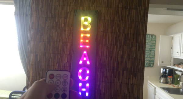
[Warrior_Rocker’s] family bought a fancy new sign for their beach house. The sign has the word “BEACH” spelled vertically. It originally came with blue LEDs to light up each letter. The problem was that the LEDs had a narrow beam that would blind people on the other side of the room. Also, there was no way to change the color of the LEDs, which would increase the fun factor. That’s why [Warrior] decided to upgrade the sign with multi-colored LEDs.

After removing the cardboard backing of the sign, [Warrior] removed the original LEDs by gently tapping on a stick with a hammer. He decided to use WS2811 LED pixels to replace the original LEDs. These pixel modules support multiple colors and are individually addressable. This would allow for a wide variety of colors and animations. The pixels came covered in a weatherproof resin material. [Warrior] baked the resin with a heat gun until it became brittle. He was then able to remove it entirely using some pliers and a utility knife. Finally, the pixels were held in place with some hot glue.

Rather then build a remote control from scratch, [Warrior] found a compatible RF remote under ten dollars. The LED controller was removed from its housing and soldered to the string of LEDs. It was then hot glued to a piece of cardboard and placed into the sign’s original battery compartment. Check out the video below for a demonstration. Continue reading “LED Sign Brightens Up The Beach After Dark”

Absolute Overkill IKEA Lampan Lamp Hack

Sometimes too much overkill isn’t enough. [Jesus Echavarria] hacked an IKEA Lampan light for his daughter to add color LEDs, a timer, Bluetooth control over the hue, and a local override knob. The result: a $5 lamp with at least $50 of added awesomeness. Let’s have a look at the latter.

The whole lamp system is based around a PIC microcontroller and WS2811 LEDs for the color light show. Since the lamp was already built to run a 40W lightbulb, and [Jesus] wanted to retain that functionality, he added an SSR to the build. Yeah, it’s rated for 5,000W, but it’s what he had on hand.

Top-ElementsNext comes the low-voltage power supply. [Jesus] needed 5V for the PIC, and used the guts from a cheap USB charger as a quick and dirty 5V converter — a nice hack. To power the HC-05 Bluetooth module, which requires 3.3V, he wired up a low-dropout voltage regulator to the 5V line. A level-converter IC (74LVC07) gets the logic voltage levels straight between the two.

A fuse for the high-voltage power line, screw-terminal connectors all around, and a potentiometer for manual override round out the hardware build.

On the software side, [Jesus] set up the knob to turn on and off the built-in lamp as well as control the colors of the LED ring. That’s a nice touch for when his daughter wants to change the lamp’s color, but doesn’t want to go find her cellphone. But when she does, the SPP Pro app sets the colors by sending pre-programmed serial commands over Bluetooth to the PIC in the lamp.

All in all, a nice build, well-documented, and with enough rough edges that none of you out there can say it’s not a hack. Nice job [Jesus]! We can’t wait to see what he does next… robot lamp anyone?

Deck The Halls With A Raspberry Pi Controlled Christmas Tree

You know the holiday season is getting close when the Christmas light projects start rolling in! [Osprey22] is getting a jump on his holiday decorations with his Christmas Tree light show controlled by a Raspberry Pi. Yes, we know he could have done it with an Arduino, or a 555, but the Raspi makes for a convenient platform. With a WiFi module, code changes can be made remotely. The Raspberry Pi’s built-in audio interface also makes it easy to sync music to flashing lights, though we’d probably drop in a higher quality USB audio interface.

[Osprey22’s] Raspberry Pi is running his own custom python sequencer software. It takes an mp3 file and a sequence file as inputs, then runs the entire show. When the music isn’t playing, the Pi loops through a set of pre-defined scenes, changing once per minute.

The hardware itself is pretty straightforward. The Raspberry Pi controls 8 solid state relays through its GPIO interface. 8 strings of lights are more than enough for the average tree. [Osprey22] topped the tree off with a star made of wood and illuminated by a string of 25 WS2801 RGB LED pixels.

Click past the break to see [Osprey22’s] tree in action!

Continue reading “Deck The Halls With A Raspberry Pi Controlled Christmas Tree”

IPhone-Controlled Daft Punk Helmet

A few years ago, [Marc] had access to a really big, very expensive 3D printer. Daft Punk helmets were – and still are – extremely cool builds, so with a bit of modeling, [Marc] and his friend [Alex] put together a model and printed out a Daft Punk [Thomas] helmet with the intention of turning it into the keystone of a great costume. A few things got in the way, and the [Thomas] helmet was left on a shelf for a few years. Fast forward to a few months ago and [Marc] took up the project again. The result is a 3D printed Daft Punk helmet loaded up with 320 WS2811 LEDs.

The 3D printed helmet was modeled well and printed in polycarbonate, but with any extrusion-based printer, there will be ridges and layers to sand, fill, prime and paint. This task was delegated to another friend, [Shaggy], while [Marc] got busy on the electronics.

The LEDs for the visor and ‘earmuffs’ are WS2811 LEDs, but not the SMD versions we’re so used to seeing. These are 8mm through-hole LEDs mounted in a lasercut piece of acrylic. Control of the LEDs is done with a Teensy 3.1 with [Paul Stoffregen]’s OctoWS2811 library. With the matrix wired up, batteries installed, WiFi capability added, and the helmet painted (not chromed; that will probably happen later, though), [Marc] had a copy of the [Thomas] helmet controllable through an iPhone.

If you’d like to check out more of [Marc]’s work, we posted something on his RGB LED suit and pneumatic Star Trek doors a few years ago.

Video below.

Continue reading “IPhone-Controlled Daft Punk Helmet”

Bike Persistance of Vision

Simple POV Bike Effects With WS2811 Strips

[Andrew] wrote in with a new take on the classic persistence of vision bike spoke hack. While many of these POV setups use custom PCBs and discrete LEDs, [Andrew]’s design uses readily available off-the-shelf components: WS2811 LED strips, an Arduino, an Invensense IMU breakout board, and some small LiPo batteries.

[Andrew] also implemented a clever method of controlling his lights. His code detects when the rider taps the brakes in certain patterns, which allows changing between different light patterns. He does note that this method isn’t incredibly reliable due to some issues with his IMU, so now he senses when the rider taps on the handlebars as well.

If you want to build your own bike POV setup, you’re in luck. [Andrew] wrote up detailed instructions that outline the entire build process. He also provides links to sources for each part to make building your own setup even easier. His design is pretty affordable too, coming in at just under $50 per wheel. Check out a video of [Andrew]’s setup in action after the break.

Continue reading “Simple POV Bike Effects With WS2811 Strips”

A collection of boards that make up the LED Jacket

A Very Bright LED Jacket

Last year, [Ytai] went to Burning Man for the first time. He was a bit inexperienced, and lacked the lumens to make him visible on the Playa. This year, he made up for it by building an extra bright LED Jacket.

The jacket consists of 48 LEDs, at 150 lumens each. Each RGB LED module was placed on its own PCB, and controlled by the tiny PIC12F1571 microcontroller. This microcontroller was a great fit since it has three PWM channels (one for each color) and costs 50 cents. Firmware on the PIC allows the boards to be daisy-chained together to reduce wiring. This was done by using a protocol similar to the popular WS2811 LEDs.

Assembling 50 of the boards presented a challenge. This was addressed by using surface mount components, a solder stencil from OSH Stencils, an electric skillet, and a good amount of patience. The final cost of each module was about $3.

With 50 of the boards assembled, a two layer jacket was sewn up. The electronics were sandwiched between these two fabric layers, which gave the jacket a clean look. A wrist mounted controller allows the wearer to select different patterns.

For a full rundown of the jacket, check out the video after the break.

Continue reading “A Very Bright LED Jacket”

WS2812 at 670 kHz

Driving WS2812B Pixels, With DMA Based SPI

Typically bit-banging an I/O line is the common method of driving the WS2812B (WS2811) RGB LEDs. However, this ties up precious microcontroller cycles while it waits around to flip a bit. A less processor intensive method is to use one of the built-in Serial Peripheral Interface (SPI) modules. This is done using specially crafted data and baud rate settings, that when shifted out over the Serial Data Out (SDO) pin, recreate the needed WS2812B signal timing. Even when running in SPI mode, your hardware TX buffer size will limit how many pixels you can update without CPU intervention.

[Henrik] gets around this limitation by using peripheral DMA (Direct Memory Access) to the SPI module in the Microchip PIC32MX250F128B microcontroller. Once properly configured, the DMA controller will auto increment through the defined section of DMA RAM, sending the pixel data over to the SPI module. Since the DMA controller takes care of the transfer, the micro is free to do other things. This makes all of DMA memory your display buffer. And leaves plenty of precious microcontroller cycles available to calculate what patterns you want the RGB LEDs to display.

Source code is available at the above link for those who would like to peruse, or try it out. This is part of [Henrik’s] Pixel Art Project. Video of DMA based SPI pixels after the break:

Continue reading “Driving WS2812B Pixels, With DMA Based SPI”