Two Wire Sensors On LED Strips

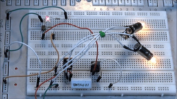
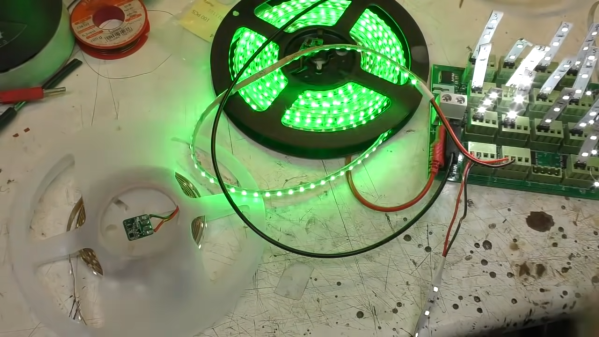
While addressable LED strips are all the rage, [Mike] from [mikeselectricstuff] has been working on an installation using the more basic two-wire strips that are simply controlled via PWM dimming. He’s recently figured out a tidy way to send sensor signals down these strips without adding any additional cabling.

Schematic for hooking up a sensor
The circuit in question.

The build uses 24 V LED tape, which consists of gangs of 6 LEDs in series with a forward voltage of 3V. Thus, these strips don’t even begin to light until approximately 18V is across them.

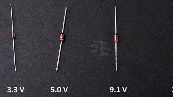
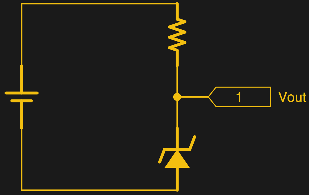
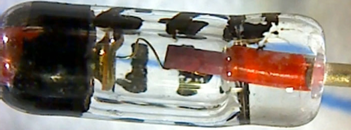
By adding a 15 V Zener diode and a resistor across the MOSFET which dims the LEDs, a voltage of around 9 V can be put across the LEDs without lighting them up when the MOSFET PWM dimmer is in its off phase. A PIC10F322 microcontroller and an accelerometer can then be run from this voltage, with the aid of a 3.3 V regulator wired in parallel with the LEDs. The regulator must also be able to handle the full 24 V when the LEDs are switched on.

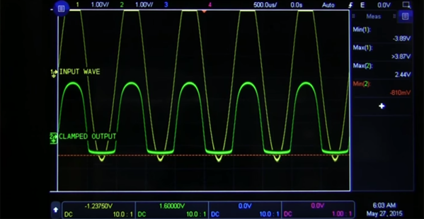
A transistor is also wired up, switching a 2.2 K resistor in parallel with the LEDs. When turned on by the PIC, this transistor causes roughly a 10 mA current to flow through the Zener diode and its series resistor. The voltage developed across that series resistor can be measured as the transistor is turned on and off. In this case, the pulse width used to turn that transistor on is relative to motion detected by the accelerometer on the end of the LED strip.

Turning the LEDs on at 100% duty cycle prevents the system working, as the pulse widths generated by the sensor circuit can’t be detected when the LED line is held high all the time. However, in practice, it matters not — running the LEDs at a maximum 98% duty cycle eliminates the issue.

It’s an ingenious way to send sensor signals down a two-wire LED strip, even if it does take a second to wrap one’s head around it. It also seems to do a great job of adding motion-reactive effects to the LED strips in question. It’s not the first LED project we’ve seen from [Mike], either. Video after the break.

Continue reading “Two Wire Sensors On LED Strips”

Zener Diode Tutorial

We always enjoy [w2aew’s] videos, and his latest on zener diodes is no exception. In it, he asserts that all Zener diodes are not created equal. Why? You’ll have to watch the video below to find out.

Zener diodes are one of those strange items that have several uses but are not as popular as they once were. There was a time when the Zener was a reasonable way to regulate a voltage inexpensively and easily. Unfortunately the regulation characteristics were not very good, and the power lost was very high. But that was sometimes a reasonable trade, compared to putting a pass transistor and the associated discrete circuitry in place to make a linear regulator. With the advent of chips like the 7800-series regulators, you can have a high-quality regulator with one extra wire and still keep your costs under $1. Even if you want to do better and go with a switching power supply, that’s easy now and not much more expensive.

Continue reading “Zener Diode Tutorial”

High Voltage Switching With MOSFETs

Using a MOSFET as a switch is generally pretty simple. Make the gate voltage sufficient with respect to the source and current flows through the channel. However, if you are switching higher voltages, you may need some additional circuitry to protect the device’s gate and possibly the microcontroller driving the whole thing, too. [Lewis] discusses high voltage switching in the latest in his series of videos dealing with MOSFETs. You can see the video below.

You’ll see in the video a breadboard setup driving a 50 V load and also a higher-voltage H-bridge. There are three major topics covered: Using an optoisolator, using a gate bleeder resistor, and using a zener diode to limit gate voltage.

Continue reading “High Voltage Switching With MOSFETs”

A Lesson On Zener Regulators

For the longest time, Zener diode regulators have been one of those circuits that have been widely shared and highly misunderstood. First timers have tried to use it to power up their experiments and wondered why things did not go as planned. [James Lewis] has put up a worth tutorial on the subject titled, “Zener Diode makes for a Lousy Regulator”  that clarifies the misconceptions behind using the device.

[James Lewis] does an experiment with a regulator circuit with an ESP8266 after a short introduction to Zener diodes themselves. For the uninitiated, the Zener diode can operate in the reverse bias safely and can do so at a particular voltage. This allows for the voltage across the device to be a fixed value.

This, however, depends on the current flowing through the circuit which in turn relies on the load. The circuit will work as expected for loads the draw a small amount of current. This makes it suitable for generating reference voltages for microcontrollers and such.

To make a Zener into a “proper” voltage regulator, you just need to buffer the output with an amplifier of some kind. A single transistor is the bare minimum, but actually can work pretty well. You might also add a capacitor in parallel with the Zener to smooth out some of its noise.

Zener diodes are wonderful little devices and write-ups like these are indispensable for beginners and should be shared more often like the Zener and Schottky Tutorial and Diodes as a Switch.


An Introduction To Zener Diodes

[Afroman] is back again with another great tutorial video on the basics of electronics. This time it’s zener diodes.

Page three or four of every ‘beginners guide to electronics’ covers a diode as, “a component that only allows current to flow in one direction.” This is true; a diode only allows current to flow in one direction. However, like any depth of knowledge, the dialectic of diodes quickly turns to a series of, ‘but..’ and ‘however…’ statements.

A zener diode is like a normal silicon diode, where a forward biased diode will pass current with a ~1 volt drop. When a zener diode is reversed biased, there’s a different voltage drop, annotated as Vz on the datasheet. When reversed biased, current cannot flow across the diode unless the voltage is above Vz. This is what makes zeners useful for a bunch of applications.

[Afroman] goes over a few of the most useful applications of zeners, including a diode clamping circuit. This circuit will clamp the voltage to a maximum of Vz, helpful when you’re feeding a signal into an analog input. This voltage clamping circuit can be used in some interesting applications. If you feed a sine wave or other signal though the circuit, you can clip the signal.

Zeners can also be used as a very crude, low current, low accuracy power supply. If you’re looking for a voltage regulator for a microcontroller that’s impossibly easy and you’re all out of 7805s, pick up a zener. It’s not the basis of a good power supply, but it does work.

Video: The Lowly Diode — Umpteen Functions With Only Two Pins

The lowly diode, a device with only two leads, can nonetheless do many things. Diodes can detect, rectify, suppress, emit light, detect light, change capacitance, emit microwaves and more. This wide range of use means diodes are included in almost every design and it’s well worth learning more about the inner workings of all kinds of diodes.

My introduction to diodes started like many of my generation with a homemade crystal radio set. My first diode was a piece of pencil graphite in contact with an old fashion safety razor with the joint of the two dissimilar materials — graphite and steel — creating the diode. In this configuration the diode is said to be “detecting” which is the act of turning a weak radio signal into a weak audio signal. At least in my home town of Marion Indiana, one radio station was stronger than the other so that I didn’t have to listen to two stations at once.

Germanium Glass Diode
The venerable 1N34A Germanium Signal Diode.

I eventually learned about “real” diodes and the 1N34A Germanium diode was my “goto” diode into my teens. Nowadays looking into a modern version of the 1N34A you can still see the semblance of the old “cat’s whisker” by looking carefully into the diode.

A quick and somewhat inaccurate semblance of the way a diode works can be demonstrated with marbles and jacks representing negative electrons and positive “holes”. Holes are basically an atom missing an electron due to the combination of elements, a process known as doping. Join me after the break for the explanation.

Demonstrating a PN Junction with marbles and Jacks.

Continue reading “Video: The Lowly Diode — Umpteen Functions With Only Two Pins”

Beginner Concepts: Powering Your Projects

Powering your gadgets generally seems like a necessary evil. To help with this [Felipe La Rotta] made a really nice bench power supply using a PC power supply and a LM317 adjustable voltage regulator. PC power supplies are an example of a switched power supply(more on that later).  The LM317 is a type of linear voltage regulator that allows for adjusting the output voltage by varying some resistors. Whats the best way to power your circuits? well that depends…

Continue reading “Beginner Concepts: Powering Your Projects”