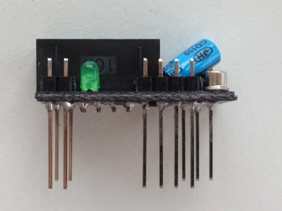
It’s not that breadboarding AVR circuits is difficult. But you have to admit that it takes some time to set everything up. We don’t label the top of our DIP chips so that you know what each pin does just by looking. Which means that wiring up the programmer involves pulling out the datasheet. [Vinnie] found the solution to this problem which is to make one of these interface PCBs for each AVR chip family. The long pins make it easy to drop over the top of your microcontroller, which is where the name comes from.
His first stab at the idea was just a hunk of home etched PCB which broke out the programming pins into the 6-pin ICSP standard. This second rendition uses the 10-pin standard and adds a few extras into the mix. He included decoupling capacitors which need to be used in every circuit anyway. There’s a crystal along with its load capacitors. This clock source is a snap to enable by burning some fuses. If you choose to use the internal oscillator instead this hardware won’t interfere. The LED is used to get you up and running with blinky firmware as quickly as possible. He plans to add jumper in the next revision which can disconnect this components from the I/O pin. Now you just need to add a 10-pin header to that USB keyboard AVR programmer and you’re in business.


Nice idea. I would replace the 10 uF electrolytic with a nice small ceramic one. You can get 10V, 10 uF in 0603 shape, and there’s even more choice in 0805. Another option would be to add the CPU on the board itself, which would be nice for experimenting with small pitch SMT stuff on a breadboard.
I made something similar for 8 pin AVRs. Comes with layout.
https://github.com/cpldcpu/BB_ISP
Clever, haven’t seen it done that way before. The only small downside is that occasionally I use my finger to check the temperature on the MCU, and the Straddler blocks access.
Why do you need to feel if it gets hot? I hever had an AVR processor getting hot, or any small low performance CPU for that matter…
It shouldn’t get hot, or even particularly warm, unless something is wrong. Touching the chip is a primitive but expedient method of making sure it isn’t being stressed by excessive current draw or overvoltage clamping on a pin.
I do the same thing. I always touch the chip. Also why is he using the 10pin header and not the 6pin?
I suppose you could add an analog temperature sensor or thermistor to it, positioned so that the sensor/thermistor physically touches the microprocessor package below it. Then you could wire it so that it makes an LED (red, of course) brighter the hotter it gets (lets more voltage through, for instance). Right?
Too bad it isn’t OSH
The comment above was actually meant to go here.
I made something similar for 8 pin AVRS as OSH:
https://github.com/cpldcpu/BB_ISP
There is a link for the brd on his page.
I wonder how seriously he takes that little © hes got on there.
There’s a difference between open source and public domain. Open source does not preclude a copyright at all.
Brilliant! Maybe a reset button/switch?
I created something similar a while back. My main focus was to make it easier to program while breadboarding, and to not have to continually look up the Arduino pin mappings. I didn’t put on the crystal or any of the capacitors in my original design though.
Now when I whip up a quick prototype using perfboard, I end up just putting headers in for these boards to go in over top of the chip. Rather than doing the extra work of putting the ISP header in the perfboard.
http://forum.arduino.cc/index.php?topic=100164
With very long pin headers this can even be achieved with a perfboard (and you can even use a pinky to check the temperature as a commenter was doing. :) Had this exact idea a few weeks ago myself: http://codeandlife.com/2013/07/20/diy-attiny4585-isp-header/
I made one of those a few years ago for 48/88/168/328 atmegas. Has some on board LEDs, an ISP header, and a MAX232.
Shitty pic:
https://lh3.googleusercontent.com/-Ds8w0Pg1o6Q/T6B4BsQkSbI/AAAAAAAAcHk/fiNC7jPN_M8/s800/photo%25202.JPG
Nice idea, but with a small addition:
While breadboarding I had some intermittent bugs. After a lot of debugging I found out that the bug always occured at the moment that the pin next to the crystal changed logic state. The capacitive coupling via the breadboard was so big that the crystal, and with it the avr, went crasy.