A few folks over at Carnegie Mellon have come up with a very simple way to do high-speed motion tracking (PDF) with little more than a flashlight. It’s called Lumitrack, and while it looks like a Wiimote on the surface, it is in reality much more accurate and precise.
The system works by projecting structured light onto two linear optical sensors. The pattern of the light is an m-sequence – basically a barcode where every subset of the m-sequence is unique. By shining this light onto a linear sensor, Lumitrack can calculate where the light is coming from, and thus the position of whatever is holding the light.
Even though the entire system consists of only an ARM microcontroller (in the form of a Maple Mini board), two linear optical sensors, and a flashlight with an m-sequence gel, it’s very accurate and very, very fast. The team is able to read the position at over 1000 frames/second, nearly the limit of what can be done with the Maple’s serial connection.
Already there are some interesting applications for this system – game controllers, including swords, flight yokes, and toy cars, and also more artistic endeavors such as a virtual can of spray paint. It’s an interesting piece of tech, and with the right parts, something any of us can build at home.
You can see the Lumitrack demo video below.


Always good to see novel tracking mechanisms. If the linear sensor + processing chip can be made cheap enough, you could plaster at least 4 on an object and have full 6 dof absolute tracking in a limited volume.
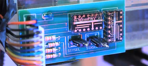
I built something similar for use in a CNC. It uses TCD1201 linear sensors that are read from an Atmega8 – you get ~500 readings per second. I used a barcode (similar to the m-sequence) printed on overhead transparancy sheets, it’s fixed in position, the sensor slides over it (attached to the gantry).
There’s one snag with these sensors: they’re rediculously sensitive.
Sensitive in what way?
sensitive is good, no?
I’d love to hear more as this was excatly the sort of application I thought of when I read the post.
The only other similar application is on printers that use a printed transparency strip to simply detect on/off transitions (think old-school mouse wheel encoder but in a long line) which is okay at doing difference motion but can’t recognise absolute (unless you regularly get to a ‘home’ and start counting again).
With 2 sensors (like a mouse), you can get quadrature information – i.e.
you are going backwards or forward and how many steps. It is a matter of
apply the deltas to the current position. No need to go to “home” unless
you sensor loses contact with the strip.
If the B&W strips are replaced with vertical barcode strips and you have
a sensor for each row, you can get the absolute location without homing
first.
mouse optics aren’t as accurate (and slower IIRC). a tcd1201 has a sensor element every 14 micrometer.
He’s talking about mechanical mice with the slotted disc. The optics were 4 IR LEDs and 4 phototransistors, 2 of each per axis (x/y). Although I recall seeing mice that only used 1 LED and 1 detector per axis. Dunno how that worked.
Anyway my point being that 4 phototransistors don’t come in the same class for “accurate” as a linear sensor, or the low-res camera that optical mice use.
You do need to go ‘home’ on each start (and if you fear you’ve missed a step) but with this scheme you don’t. And that’s what I was getting at : quadrature based is okay but you only get ‘difference’ motion (the delta from where you were), so, as to avoid the need to ‘home’ (for whatever reason), being able to extract an absolute code (all the time) is better.
In engineering terms unlike pure science, “better” usually means a trade
off between cost, reliability, performance etc. i.e. You are paying for
the resolution or convenience by paying for a more expensive part, more
fragile sensor, more firmware/hardware resources (e.g. I/O, memory)
required etc.
There is no one solution that fits to all applications. Without stating
the selection criteria and amount of trade offs that you are willing to
handle, there is rarely such a thing as “better”.
It’s like evolution by natural selection. If one thing’s better at everything, the lesser thing tends to disappear pretty quick.
Yes, sensitivity is good but the problem is stray light. In my case the sheet with the encoding is a narrow ribbon along the chassis. The sensor sits in a casing with a slit – the ribbon slides through the slit and has the sensor on one side and an led on the other.
The problem is that the slit has to be very narrow to avoid light from the outside otherwise the sensor gets saturated. the solution is to add some black foam that covers the slit and tightly wraps the ribbon. Tape the plastic ribbon to avoid ink getting rubbed off.
Btw, I started after I found this pic a while back:
http://www.flickr.com/photos/terrorchid/8802098136/
He hacked one of those eBay us asps to drive the sensor (removed USB & leds to expose enough gpios whilst keeping the SPI interface).
He’s also the same guy that wrote some code and posted pics in this thread:
http://forum.arduino.cc/index.php?topic=138585.0
Exactly the same application I first thought off even before reading the full article and comments.
Would you mind sharing some details about your rig? (i.e.: what resolution did you finally achieve with this method, repeteteability), and anything else you might consider relevant to anybody approaching the same.
Regards,
Not attempting to ridicule you but it’s spelled ridiculous.
See how I worked in a reminder? :)
This should make home based PNP machines easier I would think.
awesome find… unlike many other technologies of this type this is actually dirt cheap… can’t wait to see controllers based on it
I see 2 universities AND disney on the end, not sure how cheap it can become if they patent it.
Cool idea! I’ve messed around with these TAOS linear CCD arrays. They’re quite cool — and much easier to interface than older linear CCD arrays.
why all the talk of going home? why not just encode the position into the “barcode”? some vehicle manufacturers do this with the “toothed wheels” that read engine position so the ecu knows the angle of the crankshaft within a quarter revolution. older systems needed a full revolution i.e. home to figure out crank angle.
Very clever, and adding film to a flashlight is a very good idea.
Kind of a reversed version of this from 2007: http://hackaday.com/2007/11/15/automatic-projector-calibration/