Milling a PCB at home is a great way to save some time and money if you are making one-off circuit boards. There is a downside though, it’s a little tough. Sure, just export your Eagle design to CNC-Machine-understandable g-code and fire up your mill…. well, it’s not that easy.
The copper on a PCB blank can be anywhere from about 0.001 to 0.006 inches thick. When milling a board the ideal situation is to mill just deep enough to get through the copper but not cut too deep into the fiberglass backer board. Cutting too deep can weaken the board, break a bit, or in an extreme case, cut through the entire board.
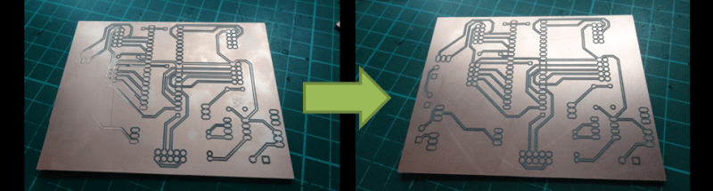
Shallow cuts can result in another problem, inconsistent cut depth over the surface of the board. Check out the left photo above. The traces on the left side of the board appears to have just faded away. This happened because the circuit board was not flat. The side where the traces are missing from is lower than the other so the tool bit is not able to reach that part of the board. Since an ideal depth of cut is about 0.010 inches, even a very small amount of waviness or out of flatness can cause a serious problem in the milling process. If you have a hard time picturing what 0.010 inches is, think the thickness of two pieces of paper, it’s not a lot. There are two main contributors to the flatness problem; the PCB board and/or the machine’s bed. If the bed is not flat, the PCB won’t be. Even if the bed is flat, the PCB may be warped or bent.
PCB fabrication enthusiast [daedelus] had this exact problem, and in true hacker fashion, decided to do something about it. He created a software program called AutoLeveller that takes a g-code file and adds a probing section to the beginning before the milling operation. When the modified g-code file is run on the CNC Machine, it first probes the surface of the PCB in a grid pattern and maps the flatness variation of the PCB’s surface. Then, when running the program, it adjusts the height of the tool bit on the fly so that the actual depth of cut is consistent over the entire board, regardless of how flat or not it is. The result is a clean and usable PCB on the first try.
There is one catch: the Machine Control Software has to be set up to accept a probe. This is easy to do if communicating to the CNC Machine via a computers parallel port. An input pin on the parallel port is pulled high with a resistor and connected electrically to the PCB board. The tool spindle is grounded with a clip lead. When the tool touches the board, the input pin is pulled low and the Machine Control Software records the tool height for that specific XY position.


Thing is, it only works with LinuxCNC or Mach3. The software won’t work with GRBL or an other DIY CNC soultions which are very popular. For TinyG there is Chillipeppr, but the grbl port does not work right so far.
I encountered the same problem with my Shapeoko, so I wrote my own toolchain for autolevelling with GRBL.
If you want to have a look at it, I just released a tutorial the other day: https://www.youtube.com/watch?v=g7A0pnUetRY
I actually succeeded in using the auto level function of ChiliPeppr with grbl. I admit the grbl workspace does not implement all functions. But management of coordinate systems can be done using direct input of gcode. Apart from that I didn’t miss anything.
You have to use the latest edge version of grbl to use probing.
The board turned out to be the best I ever made.
I am using the latest 0.9g version of GRBL, otherwise my custom program wouldn’t work. At least back when I tried it, Chilipeppr sent the next G38.2 Command while the bit was still touching the surface, so it would skip every other probe cycle.
Maybe that got fixed by now, but I’m happy with my toolchain so far. It’s just my personal opinion, but I really don’t like web apps, especially for such risky things as CNC milling.
If the board is warped, and not sitting completely flat on the bed, doesn’t that make it likely the board can accidentally shift or deflect when the bit hits it?
We built a vacuum table like an air hockey surface for the top of our CNC and for our boards we tape down all four sides, cover all the uncovered holes, and turn on the vacuum. Sucks it down and holds it in place. No software required.
Vacuum hold down table solves many many problems, and depending on the type of copper cladding and how fine your traces are it probably helps eliminate all the pragmatic problems.
For those attempting very fine traces in thin copper and wanting to minimize dulling their bits in the fibreglass, probing is still needed as the copper and the backing boards are not perfectly level. A couple years ago there was a good discussion on the pcb-gcode yahoo group about this – and there were folks milling special boards for high frequency radio work with expensive end mills that swore by the autoleveling.
For high frequency boards, depth of cut is really, really important, since the dielectric holds half or more of your signal. Cut it away and the impedance effects can be significant.
There’s actually an add-on for the high-end PCB mill from LPKF that has a pneumatic depth limiter that senses depth to crazy precision to ensure consistent cut depth for high-frequency stuff.
For those using Eagle PCB for designing boards, there is a free pcb to g-code plugin called PCB-GCODE (I uploaded a demo/how-to video 2 years ago https://www.youtube.com/watch?v=WfQTS4RDP-g)
I have the same programming setup on my 3D printer. A servo-actuated probe flips down before a print, and measures how flat the glass plate is. Then the gcode is adjusted on the fly to keep the print flat relative to the glass. Sounds like the same thing described in this article.
Nice! I cannot wait to try this.
My mill is driven by Mach3 and a G540, so I should have no trouble setting this up. I’ve thrown away many boards and dulled many tools because of this exact issue.
What I first assumed was an uneven table, since even a 1/1000th of an inch difference can make a big difference when doing this kind of milling. What I did was to make a spoilboard “PCB Sled” for my table that screwed down to the table in a known location. I then milled the board flat using a surfacing tool to create a bed surface that was dead flat to the spindle.
I quickly found that this did not help, that it must have been fluctuations in board thickness. The fact that I use bulk PCB blanks purchased from the ‘bay probably didn’t help.
My solution thus far was to always purchase thick boards, set my trace widths in Eagle to no less than 0.03, and ZDOWN into the board deeper. This reduced the width of my traces considerably, so it was always a guessing game when I had power carrying traces where trace width was a concern, to set them in Eagle to be X, knowing that my resulting trace would be “something less than X.” Of course this also severely limited what I could successfully mill… traces running between pads of a DIP IC was basically an impossibility for me, meaning I had to do lots of jumpers and crap on my boards that was frustrating and sloppy. SMT was a fantasy.
So I’m excited to see how this works.
I love at the 3 min mark you can see the z motor moving to adjust for the uneven board!
Might want to adjust the program to probe back and forth instead of resetting to 0 for each pass. Would save some time.
Why not just use a spring loaded engraving tool? Uniform cutting pressure in Z axis and no need to probe.
I run a HAAS CNC mill with 26″ x 50″ solid 3″ thick aluminum vaccuum table for a living. I regularly face large sheets of plastics, composites, and even special plywood for the transformer industry flat.
I have seen problems with using spring loaded tooling to account for height differences on workpieces using my vaccuum table setup where only 0.002″ over 50″ makes a big difference. Actually, saw that today.
Occasionally I have jobs that need precision pen alignment marks on them, engraving marks are not allowed. So we created special tapered holders for Xtra fine sharpie markers using sponges as a very fine spring. I was doing one of these jobs today, and I adjust the pen to just start ink flow at 0.001 depth from top of part. Parts are faced very flat using special tooling developed for the particle board industry.
I saw adjustment of 0.002″ over an area of 10″ or so, about 1/5 my part length on one axis, be the difference
between not writing, and writing. The sponge is very sensitive as a spring, and must be, because sharpie markers wear out very fast if you put any more pressure on them than needed to write under straight-down pressure.
I’ve seen it before, in areas of my table, when I have my tooling setup really well- some areas are only 0.001 higher
than the rest of the table.
If you use spring loaded tooling to control milling, you had better be sure your table is absolutely dead flat, and
that your spring is extremely sensitive. Otherwise, there is no way any tool you use spring loaded will ever repeat to a truly exact depth over a workpiece that is anything less than perfectly flat.
Nice. Wonder if I can implement it on other surfaces for milling, using some foil to simulate the ground plane?
Cool idea. I bet you could make a simplified version of auto-level that just rotates the coordinate system using G68 to account for misalignment. I have never done this but apparently it is a common operation for this exact problem. It would assume the PCB is planar though so it might not work in cases where you have random lumps. I have also heard of spring loaded engraving heads to account for variations in height.
Er, but aren’t there also dynamic issues? For example, the milling process will generate heat in small areas as the milling is taking place. Fiberglass is not homogenous – it contains varying amounts of mat material vs. resin throughout its volume, which could then expand at different rates at different places on the board due to the heat from milling. Would it not be best to measure Z before each cut? Or even concurrently with each cut, in real-time?
I’ve never done any milling, or really any CAM work. I’m just wondering if even a static measure beforehand could be invalid after a few cuts.
It’s neat when a computer can fix human error but should you not just level and resurface the milling bed?
According to the article, he did and that’s when he discovered that his PCB material isn’t perfectly flat.
Old school hand drilling operations utilized locking collars to ensure drill depth. Couldn’t someone make a foot that rests on top of the pcb right around the cutter and allow the cutter to float in the Z axis? Then the depth of cut is limited by a stop on the foot, and your gcode simplifies to something akin to a pen plotter just lifting and setting down the tool.
LPKF use exactly the system you describe for their Protomat mill. It’s an elegantly simple and effective solution, resulting in very precise milling depth (and width, with conical cutters). The shoe does leave burnish marks on the copper. Here is a photo gallery of a Protomat 92s; you can (barely) see the shoe in the fourth picture. The knurled thumbwheel adjusts the collar height relative to the tool.
http://reboots.g-cipher.net/lpkf/
From a machinist’s standpoint, spring loaded tooling is done (see my comment above), but if you have a way to do it, probing your part’s surface as a fine grid, and having the control adjust the Z depths at according locations on your part would be the most accurate way of getting a consistent depth of cut.
I know there are some crazy-hyper precise mills, stuff like a Kern Pyramid Nano maybe, that use infrared tooling sensors to measure tool heights and diameters- some even measure the capacitance between tooling and workpiece. Perhaps someone could rig up a very sensitive capacitive probe that connects to the tool shank in the spindle by spring pressure, and measures the capacitance between it and the pcb, via a small grounding wire between the milled surface to the machine’s metal casting. This capacitance would give the Z axis servomotor supplementary input to adjust Z depth in real time at exact current tool coordinates for completely exact depths of cut in PCBs.
Anyone want to do that and write an article? I’ve never seen it before, but my electronics ability is poor, or I’d do it.
How about a spring loaded tool with a non-rotating UHMW shoe around it? Have the tool to shoe height fixed and that assembly able to float a few thousandths. A vacuum to pull the chips out would be needed.
Running the probe back and forth would go a bit faster than returning to start all rows from the same side. Or upgrade the machine with much faster rapid move capability.
ALGUIEN SABE COMO USAR EL AUTOLEVELLER EN LA VERSION 0.9.5??