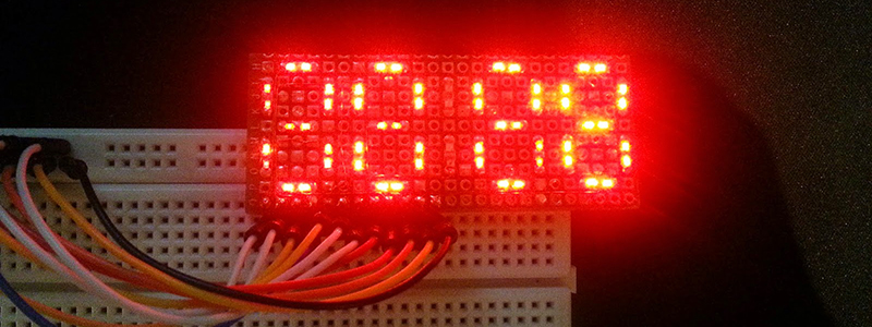
[Esai] wanted to build an electronic clock from scratch. A noble quest, but ordinary seven-segment displays are just that – incredibly ordinary. Instead of a few displays that can be bought from the usual retailers for a dollar a piece, [Esai] made his own four digit, seven-segment display on some perfboard.
Before soldering 58 SMD LEDs to a small rectangle of perfboard, [Esai] traced out each segment with a marker. Two LEDs make up each segment, and they’re all connected to a breadboard-friendly pin header with 30 gauge wire.
Each segment is connected as a single column in the LED matrix, and each digit is a row. It’s a simple design, but there aren’t any resistors on this board. Hopefully [Esai] will be using a proper LED driver with this display; you really don’t want LEDs to burn out twice a day at 1:11.


That’s why 24-hour clock is better. The leds will burn only once a day.
I’m scratching my head as to why 1:11 ?
The least number of LED’s powered on at one time (maximum current) ?
1= 4 LED’s on
7=6 LED’s on
4=8 LED’s on
2 =10 LED’s on
3=10 LED’s on
5=10 LED’s on
0=12 LED’s on
6=12 LED’s on
9=12 LED’s on
8=14 LED’s on
Should’ve been 4:20!
Because 1:11 is when the fewest number of leds are on. I’m guessing they are saying that without properly driving the leds you could burn them out by overdriving them.
…or burn out whatever chip is driving them. Unless your driver chip has some form of internal current limiting, you could have a high enough LED current to blow either the LEDs or the driver.
But I can understand “what drives a man” to build his own 7-segment displays. For example, Charlieplexing is a way to drive many LEDs with few I/O pins. But it requires displays that do NOT have a common, so you can wire the individual LEDs in the matrix needed for Charlieplexing. As far as I know, no one sells 7-segment LEDs that aren’t either common-cathode or common-anode (i.e. with all the LED lead brought out separately).
Commercial 7-segment displays don’t have resistors either. [Brian] apparently put some thought into this – yes, at 1:11 the least number of segments is lit. But unfortunately it’s based on a false starting assumption. This DIY display is driven just like any other, and has no special driver conditions or requirements.
The way I implement a 7-segment driver is to only energize a single segment at a time. This prevents any numeric digit from consuming more current (“8” same as “1”), and altering the digit’s intensity as a result. This arrangement only requires 11 I/O lines: 4 digits + 7 segments. It requires sufficiently quick multiplexing, 1680Hz min. Another key to maintaining uniform intensity is to divide the time per segment equally, regardless of whether or not a segment is illuminated during that segment’s cycle. This approach drastically reduces total circuit current consumption, too. On my LED watch, I got my total current consumption under < 5mA. This also simplifies the circuit, as only a single current-limiting resistor is necessary per digit.
As stated by [Chris C.], it’s built like a commercial display, just leds without any control circuit.
The visual diference in brightness is from the leds being at different angles and the bad connections on the breadboard.
Fortunately this was just a side project and the display will not be used for anything major. I will be building a seperate clock later with a nice pcb and a microcontroller. Just wanted to share the idea with the community.