
Last session, we use the cheap and cheerful 4046 Phase-locked Loop chip as a simple voltage-controlled oscillator (VCO). It was dead simple, in fact, because the chip has a VCO already built in. There’s one big drawback of the 4046’s VCO; the pitch changes linearly with the control voltage. Ideally, as we’ll discuss in the next sections, we’d like the frequency to be an exponential function of the control voltage (CV), and that’s going to mean a little bit of analog circuitry.
René Schmitz has a fantastic exponential VCO design that’s almost a perfect fit for the Logic Noise series — it’s built with a minimum of parts, it’s a little bit rough around the edges, and at its core is a 4000-series CMOS chip that’s normally used for digital logic applications. The only drawback, from our perspective, is that it uses a dual (positive and negative) power supply. We’ll hack our way around that, and ignore some of René’s otherwise worthwhile refinements in the name of doing something truly quick and dirty. We’ll get 95% of the results with 70% of the work, although it’s easy enough to add on the rest if it strikes your fancy.
Let’s start off with a little scale theory.
Why Exponential Voltage Control?
We humans hear pitches on an exponential scale. All of the musical intervals that we’re used to are based on multiplications and divisions of the fundamental frequency. For instance, we think of the scale repeating every octave, by which time the pitch has doubled. If you multiply the base pitch by 3/2 instead, you’ve got a “perfect fifth”, so-called because it’s the fifth degree of an eight-note major scale based on the initial pitch. To make a (perfect) major chord, you combine the root note with a fifth and a third, which has a frequency that’s 5/4 times the root note’s frequency. It sounds “in tune” because different harmonics that make up the sound line up.
As a concrete example, imagine you’re playing a concert “A” at 440 Hz. You can play an octave up by playing 880 Hz, or an octave down by playing 220 Hz. A fifth up is an “E” at 440 * 3/2 = 660 Hz. The third comes in a 440 * 5/4 = 550 Hz. All this is to say that musical intervals are all about ratios of frequencies.
On the electrical side of things, however, it’s much easier to add and subtract voltages than it is to accurately multiply them. We saw this with our active mixer circuit, for instance. If you simply run two signals through equal-value resistors into the input of an amplifier with feedback, you get the sum of the two input voltages. Multiplying voltages requires a much more complicated amplifier setup. This mismatch between multiplicative frequencies and additive voltages is what makes linear voltage/Hertz scaling awkward. But there’s a second problem that’s even worse.
In our example, if you want to go from an “A” to a “C”, you have to raise the pitch by 440/4 = 110 Hz. You can figure out the corresponding voltage increment and you’re all set. If you started out an octave down, at 220 Hz, however, you’d get a “C” by adding 220/4 = 55 Hz, so you only need to add half of the former voltage. The main problem with linear voltage scaling is this doubling and halving. As you play up and down the keyboard, the voltage increments necessary for any given interval become either tiny or gigantic. Replicating a piano’s range with a half-step at the bottom end represented by 10 mV, which is about the least you could get away with, means that a half-step at the top needs 1.6 V and the total range is just under 27 V. It’s your basic rice and chessboard problem.
We get the VCO to internally exponentiate for us so that we can control the VCO from the outside with nice linear voltages. Following the de facto standard in the synth world, we’ll set up the oscillator so that adding one volt to an input will double the pitch of the output, raising it up by an octave. If you want to play a fifth, you add half a volt, regardless of where you are in the scale. If you want an equal-tempered scale, you only need to reckon down to twelfths of a volt, and the voltage increments are the same no matter where you are on the keyboard.
In short, exponential voltage-to-frequency scaling makes the electronics that corresponds to musical intervals a lot easier. So let’s do it.
Expo Converter
The exponential converter in the VCO takes advantage of the fact that it’s dead easy to get an exponential current to flow through a transistor in response to an input voltage. And once you have exponentially-scaled currents flowing, all that remains is to build an oscillator where the frequency is controlled by a current. That’s the plan, anyway.
The basic model of a bipolar transistor that everyone knows and loves (maybe) is the Ebers-Moll equation:

where IES is a constant that depends on your particular transistor and temperature, VBE is the voltage applied across the base and emitter, and VT is another constant that depends on temperature. For now, think of these constants as being constant, but don’t forget that we just said the word “temperature” twice.
So here’s an exponential voltage-to-current converter: it’s just a transistor. And here’s how the voltage response looks on the scope, with input voltage across the x axis and the current measured by passing it through a resistor and measuring the voltage drop. (As more current flows through the resistor, more voltage is dropped across it, resulting in a proportionally lower voltage at the measurement point.)
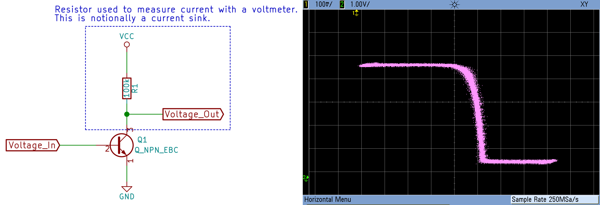
As you can see, current can’t increase exponentially forever, but stops once it runs almost into the ground supply when the input voltage reaches about 525 mV. And the transistor doesn’t even start to conduct until the base-emitter voltage gets up around 400 mV. But between those two bookends, the current surely does look to be increasing exponentially with input voltage. So the next step is to scale down the input control voltage so that it stays inside this active range where the Ebers-Moll equation holds.
If we have a control voltage range of 5 V, and we want it to fit between (roughly) 400 mV and 525 mV, the entire range fits if we divide by 25, so we’ll need to divide by at least that much. To get one volt per octave scaling, we’ll have to do some math. If we double the frequency by adding 

 VT is around 26 mV , so that’s 18 mV per octave on the input to the transistor, suggesting that we divide the input voltage down by 55 (1 / 0.018) to get one volt per octave scaling.
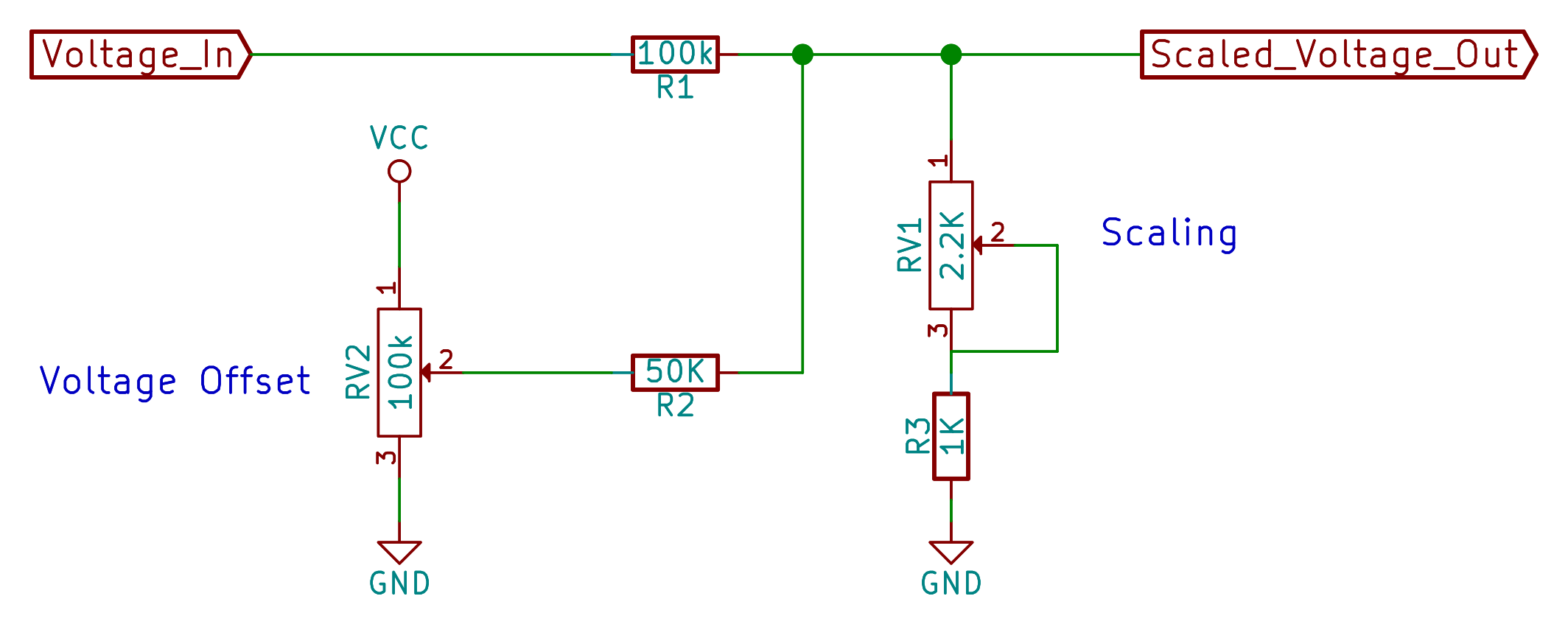
We’ll also need a voltage offset of at least 400 mV, from the look of things. We simply add in a voltage divider tied to the rails and a resistor to combine it with the control voltage through another resistor. Putting all this together, we get this scaling circuit.
Temperature Dependence
When you build this circuit, touch the transistor with your finger. You’ll notice the effect of the temperature dependency of the “constant” IES alluded to above. It’s actually quite dramatic, and removing most of the temperature drift due to IES is a piece of cake, so let’s do that now.
![]()
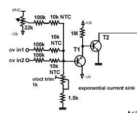
The first transistor, a PNP type, is set up as a common collector voltage follower. The current gain equation in this stage is the same as for the NPN transistor, but with a minus sign in front of the voltage, because current is closed off in a PNP transistor as the base voltage increases. And because of this minus sign, when you solve out for the overall current function, the two IES factors approximately cancel out, removing the main source of temperature dependence along with them.
If you’re feeling particularly fastidious, you can actually tape or glue the two transistors together so they’re at the same temperature which helps the temperature coefficients cancel out. Even if you do so, you’ll find that the circuit drifts around for a little while after turning it on, so give it a minute to warm up.
And notice in René’s design that he’s also included some thermistors (temperature-dependent resistors) in the CV input path. These cancel out the (second-order) dependence on temperature coming from the VT term, making the oscillator even less temperature dependent. If you’ve got 10K NTC thermistors on hand, by all means use them. Otherwise, don’t sweat the details — the circuit is already usably precise as-is.
The Single-Sided Supply Fudge
Hey, what’s up with those two diodes, D1 and D2?
 In René’s design, the PNP transistor and the offset voltage divider are connected to a negative voltage supply, while the NPN transistor and the input scaling potentiometer are connected to a mid-rail ground. Since we don’t really have a mid-rail ground voltage, we’ll have to fake one. And since we potentially don’t have all that much voltage headroom, for instance the circuit is running on 4xAA batteries, we’ll set up this fake mid-rail at an only slightly higher voltage than our ground reference.
The trick with dual and split-single power supplies is that all voltages are relative. If we call one voltage “ground” or 0 V, then all other voltages are measured with respect to that one. We’ll take the most negative voltage we’ve got (our “ground”) and substitute it wherever we see a negative voltage in René’s circuit. Everywhere we see a “ground” in René’s circuit, we’ll need to raise the voltage up a little bit.
We do this quickly and dirtily with diodes. A diode drops around 0.6 V when conducting, so we’ll put a diode pointing downwards between our ground (the most negative voltage in the circuit) and the scaling potentiometer and collector of the NPN transistor Q1 respectively. The scaling pot is fine as is, but since a diode only drops 0.6 V reliably when current is flowing through it, we need to bias the diode on the NPN transistor so that it’s always conducting by adding a resistor to VCC. Now the “ground” level for the PNP transistor is lower than the NPN transistor, and we get a much better exponential scaling at lower voltages. You’ll still notice that it’s not perfect in the lowest ranges, but it’s better than nothing.
Current Controlled Oscillator
We’ve now got a transistor circuit that pulls an amount of current that’s exponentially related to a reasonable CV range. All we have to do is build up an oscillator to go with it. The oscillator design René uses is only a little bit more theoretically complicated than our usual 40106 oscillator, but it’s rock-solid and exactly what we need. We’ll just copy it straight up.
The overview of the oscillator is that the capacitor C1 is charged and discharged across its inverter section. The left-hand side of the capacitor charges almost immediately through the diode D1 but can only discharge slowly through the exponentiating transistor, and that’s what gives the oscillator its pitch. The oscillator roughly has these two states: slowly discharging the capacitor back out through the transistors, and super-quickly charging the capacitor back up again. The rest of the circuit just supports the speedy charging.
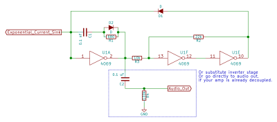
The pair of inverters hooked up in feedback on the right-hand side of the circuit (U1F and U1E) form a Schmitt Trigger.
Here’s how it works. If the input of the first inverter is high, its output is low, which means the input of the next inverter is low and its output is high. Viewed as a pair, two inverters make a non-inverter. The high input state of the first inverter is reinforced through the 22K resistor.
When a sort-of low input arrives through the 10K resistor, it’s going to be partially cancelled out by current flowing through the feedback loop. Only when the input is low enough to overcome this feedback does the first inverter turn over, and the input and output of the trigger circuit flip to the low state. The Schmitt trigger in this circuit is simply providing a source of current to quickly charge up the left-hand side of the capacitor while being immune to small amounts of noise in the circuit. Once it’s done its job charging the capacitor up, the output of the Schmitt trigger is effectively blocked from the circuit by the diode D1.
The diode and resistor inline with the capacitor (D2 and R1) can actually be left out and not much changes. The resistor is simply present to provide a current path for the capacitor through which to discharge into the exponentiator. Replacing the resistor with a simple wire results in a small voltage spike on the left-hand side of the capacitor when the inverter switches its output high. The resistor slows down the charging of the right-hand side of the cap just enough to damp out this spike.
On the other hand, we don’t want to slow down the discharge of the right-hand side of the capacitor, because that would slow down the sawtooth wave’s downward drop. The diode D2 provides a path for the speedy discharge of the capacitor when the inverter switches its output low.
Again, the snubber resistor and diode are a refinement, but together they speed up the downward-falling portion of the ramp waveform. This is important because the amount of time that it takes to discharge the capacitor doesn’t change with pitch, which prevents the pitches from tracking perfectly from octave to octave. As built, you can expect four to five octaves to stay in tune. Without the resistor and diode, you get about three octaves in tune. No big deal either way, but it’s a nice touch and only adds two one-cent parts to the design.
Finally, notice that you’ve still got three inverter amplifiers on the 4069UB to play around with. One option is to simply feed the sawtooth output into an inverter and enjoy the quick-and-dirty overdrive effect. Of course, you could go whole-hog and implement an overdrive-to-fuzz circuit, which will give you even more tonal variation.
René’s suggestion is to use the remaining three inverters to create a pulse waveform, adding another input so that you can modulate the pulse width. It’s a nice sound, but adds to the build complexity. Later on, we’ll look into waveform distorter circuits of all kinds, and building the ramp-to-pulse circuit is a great stand-alone option, so don’t be surprised if you see this part of the circuit pop up again in these pages.
Tuning
The best thing about having a one-volt-per-octave oscillator is that now you can play in tune. Or at least, you’ll be able to once you’ve tuned the thing up. Fortunately, this design has only two knobs that you’ll want to tweak to get it in tune. Unfortunately, the scaling knob is ridiculously critical and touchy, and takes a little practice to get just right.
If you’ve got a frequency counter of some kind, or maybe your oscilloscope reads out the frequency of the displayed waveform like mine does, then everything’s pretty simple. Dial in one volt on the CV input, and note the frequency. Then dial in two volts. Is the second frequency twice the first? You’re done. Is it too high? Turn the scaling knob one way. Too low? Turn it the other way. If you don’t have a frequency counter you’re going to have to use your ears, which is more of a challenge. To help out, build up this simple circuit.
 What it does is switch three voltages (determined by the three pots) through the 4051 multiplexer, the output of which is buffered by the transistor. If you’ve been following along, you’ll have all the parts you need sitting around from the second and third sessions. Plug a voltmeter into the output and set each potentiometer until the voltages read (for instance) exactly one, two, and three volts. It’s easiest to disconnect the clock generator and simply tap the signal to VCC and GND until the potentiometer that you need to set is selected. Reconnect the clock once everything’s set.
Now you’ve got a circuit that should play three octaves of the same note up and down. It’s pretty easy to get this into decent tune just with your ears if you know what you’re listening for. Alternatively, as demonstrated in the intro video, you can just tune the circuit up live with whatever you’re intending to play the VCO with. My keyboard puts out a solid 1V/octave, but if yours doesn’t, you’ll need to tune the VCO to match. The nice thing is that you have the flexibility.
Now that the octave scaling is working, you can tune the oscillator to match another musical instrument with the CV offset potentiometer. This one’s a lot easier, and you can do it by ear. You shouldn’t need to re-do the octave scaling again afterwards, but it doesn’t hurt to double-check that as well before you get up on stage with this thing. At worst, you might need to ping-pong between scaling and offset adjustments a couple times before everything’s perfect. That’s the price you pay for wanting to play in tune.
What’s next?
So now that we’ve got a tuned volts-per-octave VCO. Your homework is to wire one of these circuits up on the breadboard and play around with it. See what kind of voltage sources you have lying around and hook them up. Try a string of resistors in a row, like a multi-stage voltage divider, from VCC to GND. You might want to buffer them with a transistor circuit, but then you should be able to play them like a keyboard.
Once you’re convinced that you like the circuit, put it together in solder and wire on perfboard or something similar. It’ll probably behave better than it did on the breadboard because this circuit deals in small voltage differences and low signal voltages. This is a good module to have on hand, anyway. If you haven’t played around with modular synthesizers, this is a great first “real” step. If you have, you already know that you can’t have too many voices (or amplifiers).
Next session, we’ll look at what you can do with voltage control. Specifically, we’ll build up a digital-to-analog converter (DAC) and start playing in-tune scales and then add a shift register into the mix to make something that’s seriously more than the sum of its parts.
And if you’ve been following along, you’re probably scratching your head because I said last time that I’d retrofit the 4046 PLL oscillator for one-volt-per-octave, and then we switched up to an entirely different architecture. What gives? Circuit failure. Where this session’s oscillator has two knobs that are necessary to tune it up, the 4046 exponential converter had three, and it was just a mess getting the thing in tune. But don’t fret, we’ll see the 4046 PLL again after we spend a few sessions playing around with our brand new VCO toy.


I used the 4069 VCO for ribbon controlled instrument. It is perfectly adequate for solo playing at room temperature.
This looks like another incredible article. Can’t wait to read it more closely. Scaled control of the oscillator was ‘all that is missing’.
Thanks elliot!
Common collector (emitter follower) has the collector to common (gnd). Looks reversed in your diagram. The current gain is not the same as stated, it is simply the Vbe temperature variations which track to cancel some temperature effects. This circuit is right out of AoE. You don’t need those diodes for single supply, and in fact they contribute significantly to temperature drift. Grounding the npn emitter works just fine.
what does mean AoE?
Art of Electronics.
The schematic had the PNP flipped, as you note. I fixed it. Thanks.
Why do you think that the current gain is not as stated? I actually built the circuit and measured it, through a reasonable load resistor. The voltage-current gain is pretty much exactly what it should look like, and that’s what makes the circuit work.
Anyway, the whole point of tossing in the voltage-follower PNP stage is to cancel the (first-order) temperature dependence of the NPN transistor, which I think it does.
I wouldn’t be shocked if the circuit was in AoE. It’s probably in a lot of places. It’s also in this old Electronotes (http://electronotes.netfirms.com/s019.pdf). Read that up and let me know what you think.
The video in the “Expo Converter” section is gone. Why is that?
Great article, I’m going to read the whole series. second video link appears to be broken
Youtube ate my video! I re-encoded it and re-uploaded. Should be good now. Thanks.
Some really hard to bear sounds you got there!
Meh. The sawtooth is actually pretty clean, but in one of those examples it’s run through a not-so-great interface to my laptop and distorted pretty badly.
On the other hand, the tuning demo stuff nearly made me lose my mind. :)
Actually, on re-watching the videos, I noticed that it sounds a whole lot worse after whatever audio re-encoding that Youtube is doing. This circuit really makes a very clean sawtooth wave, which sounds as good as any other.
I’ll see what I can do about the audio codec. Hopefully I can get it to them in a format that they won’t mangle.
The PNP voltage follower has its E & C connections reversed! Might want to check the wiki it is linked to.
Ack. I flipped the PNP transistor in the diagram. I just fixed it. Thanks.
How are the 400mV and 525mV value selected ? By reading them roughly on the scope or is there a better way to find out ?
Any chance of a complete schematic? I really want to make this!
I am working on a 16-step sequencer based on all of your information (thanks by the way!) and have tried to get something working for days and days. I want to be able to tune each pot to middle C when turned all the way left and then one octave up when turned all the way right. I can get it working with individual pots but when all 16 are playing in order the tuning is always slightly off, tolerance issues I guess? How can I get all the pots to be in tune? One or tow octave ranges
Hiya!
If I understand correctly, you’ve got 16 potientiometers, used as voltage dividers, run into a switch or something, putting 16 different voltages into a/this VCO, and you want them all to put out the same voltage when the knobs are turned to the same physical positions?
As you say, tolerance will probably get you. If you can adjust the potentiometer knobs (some have set screws) you could use an ohmmeter to set them all to the same voltage and move the dials on the knobs to all be in the same place, no matter where the shafts are.
The other thing is to just tune by ear and not by eye. I.e. ignore the knob positions or treat them as rough guides to be tweaked. This is common practice even with professional analog synths. Your ear should be your guide for what’s “right” anyway.
Finally, I should admit that this VCO design is _barely_ viable. It was a stretch to fit a real tunable VCO into the Logic Noise limitations of simplicity, a single-sided supply, and CMOS ICs whenever possible. To do the exponential converter part right, you really need a source of negative voltage, and there’s not enough headroom on the high end of this circuit either. I can get like 2-3 good octaves out of it, and that’s after a ton of tweaking.
If you’re serious about tuning, build up the classic Electronotes style VCO and use a bipolar power supply or look into the just-re-released Curtis CEM chips. For like $5-10 you can buy a Curtis CEM3340 (now AS3340) that’ll do essentially everything you want in a VCO.
Hi. Fabulous series. I’ve been noodling for days. I’m ready to start smashing some of these bits together, and I’m a bit unclear on how this could interface with a 40106. I have several waveforms pumping out of that chip, but I don’t know where this hooks up.