Last time I showed you how to set up a reasonably complex design in a spreadsheet: a common emitter bipolar transistor amplifier. Having the design in a spreadsheet makes it easy to do “what if” scenarios and see the effects on the design almost immediately.
Another advantage that spreadsheets offer is a way to “solve” or optimize equations. That can be very useful once you have your model. For Excel, you need to install the Solver add-in (go to the Excel Options dialog, select Manage Add-Ins, and select the Solver Add-In). You might also enjoy OpenSolver. You can even get that for Google Sheets (although it currently lacks a non-linear solver which makes it less useful for what we need).
The Solution
I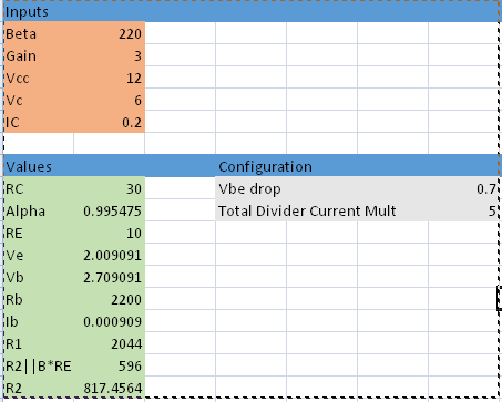 f you recall, the transistor spreadsheet (amp.xlsx on GitHub) could pick any values for the voltage divider (
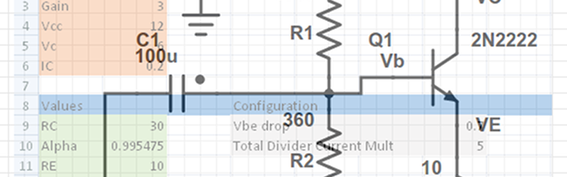
R1 and R2) as long as the ratio generated the correct base voltage. To enable it to pick one set of values, the spreadsheet has a cell to set the current multiplier (5 in the example below). This sets the total current through the divider in terms of base current. So, in this case, the base will draw 1/5 of the total current and R2 will carry 4/5, the balance.
However, 2044 and 596 aren’t standard resistor values. You can just change the divider current multiplier by trial and error to try to get R1 to a standard value. However, that’s also exactly what the solver is for.
On the Data tab you should find a Solver button (if you installed the add-in). Pressing it brings up a screen like this:

The way I have it filled out tells Excel to modify cell G10 (the divider current) until R1 is equal to 2200. In all cases, though, the value of G10 has to be at least 2. Press Solve and you will see the result in the spreadsheet. If the current divider is about 4.65, you get R1 is 2200 ohms.
Unfortunately, that sets R2 to 905.5 ohms. That’s still pretty close to 1 K. I added a sub-sheet to show the effect of using “correct” values for the dividers (but keeping nominal values for the emitter and collector resistors). You can download amp2.xlsx from GitHub.
In the case of using R1 = 2200 ohms and R2 = 1000 ohms, the collector voltage drops to about 5.6 V, a 7% error. Keep in mind, your resistors are probably no better than 5%, so that’s probably not a problem. For example, if R1 were 5% high and R2 were 5% low, VC would be 6.09 V, an error of about 1.5%. Flip the tolerance and the error goes over 16% (VC is right about 5 V, in that case).
Can your design tolerate a 16% error? It had better. Because transistor variations and temperature will make it even worse. Sure, you could tighten up the resistance tolerance and use combinations of resistors to get a closer value, but you can’t get too complacent that your model values are absolutely going to set real world parameters.
Of course, if you don’t like that, try another solver run with a different value. If you set the current ratio to about 3.4, you can see R1 is 3K and R2 is close to 1.5K. That gives a VC of 5.9V which is about a 2% error, and a worst case error of almost 11%.
More Examples
On the same GitHub project, you’ll find spreadsheets that model a voltage divider and an RC filter. These can really show off the power of the solver. Consider the voltage divider spreadsheet: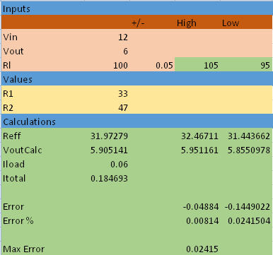
This takes into account the load resistance in parallel with R2 and allows you to vary the load by some amount (5%, in the above example). Now you can ask the Solver to do things like minimize the error while keeping VoutCalc the same as Vout, for example.
Consider this scenario: You ask the solver to minimize the maximum error cell (D18). You allow it to modify cells B7 and B8. Use the following four constraints:
Vout=VoutCalc- _
R1>=10 - _
R2<=47000 - _
R2>=10
Now when you solve, you’ll get the best resistor values from the standpoint of accuracy (10 and 11.11 ohms). By changing the constraints, you could ensure you get the answer you need.
Spread ‘Em
Of course, if you really want to do a lot of sophisticated math modeling, there are plenty of choices. However, it is hard to beat the widespread availability and ease-of-use of a spreadsheet. Next time you are reaching for your calculator–or, if you are like me, your slide rule–maybe open a spreadsheet instead. You can always use your spreadsheet to develop complex waveforms, too.


I have made few php scripts that do the similar stuff. They are in finnish language but you get the point quite fast..
Find simple RC lowpass: http://on.tuu.fi/laskuri/elektroniikka/alipaasto.php
Find a voltage divider resistor set: http://on.tuu.fi/laskuri/elektroniikka/jannitejakoetsin.php
Nice. This place has a lot of calculators in one place: http://www.calculatoredge.com/index.htm
With VBA, you can pretty much program office to be your bitch and do anything. But really, office is NOT engineering software, even when its all some of us have an all we’ll ever get because of stupidity on the part of the powers that be. So instead of pulling up an advanced piece of design software, I have to get out excel and waste hours and days of time trying to make it do something that would have taken me five minutes elsewhere…
If its all you have or cannot afford a license to something better, it will work much of the time. But I could also do my own dentistry and surgery at home too. However; I think I’ll stick with people with medical degrees for those kinds of things, it works better that way.
On the topic of optimization, for a future installment of working with LTSpice could you go over using ASCO with it?
With modern Google App Script Add-ons, you should be able get a solver pretty easily. It exposes a JS env with hooks into the Sheet. See https://developers.google.com/optimization/lp/add-on.
I have too many bad memories of investing in a Google scheme only to have Google deprecate the whole thing about the time I become proficient in it (Althought Google spreadsheet has a few things in it that Excel should copy)..
But I’ll stick with Excel and VBA. A decade ago I did some GIS stuff, and used VBA to interface an Excel spreadsheet of voter data to a precinct map in TurboCAD. It was a little bit tricky (TurboCAD didn’t document their interface too well), but years later, even after a few Excel and TruboCAD upgrades, the code still worked well.