In the past, [Sjaak] has had his testing and programming jigs made for him in Shenzhen, but realized they weren’t that great of a value. They weren’t terribly expensive in the grand scheme of things, but they didn’t include any wiring, so he was still spending his own time and money. His quest to develop his own in-house jigs not only netted him a considerable cost savings in the end, but also produced a nicely detailed post on his site for anyone else who may be heading down the same path. That’s a win-win in our book.
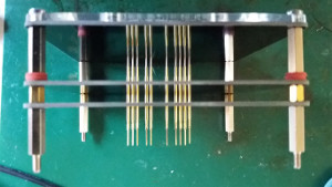 The idea behind a jig is pretty simple: essentially it’s just a mount that holds the PCB, and a set of pins which contact the appropriate points on the board. The jig can then provide power, programming, status LEDs for testing, etc. Basically anything that you can’t or don’t want to include on the final board, but will help in testing or programming them.
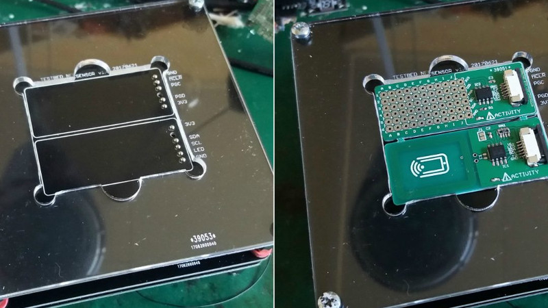
To start, [Sjaak] begins with a blank PCB in Eagle and imports his target board. With the two lined up, he can then mark where he wants the pins to go on the jig, and add labels to the silkscreen to make things a little easier during diagnostics. The target board is then removed, the file converted to Gerber, and it’s sent off for manufacturing. With a few more tweaks, the file is then exported to DXF and laser cut out of acrylic. When the PCBs come back, it’s just a matter of sandwiching it all together with some standoffs and adding the pins.
[Sjaak] mentions that he was inspired by an old post on how SparkFun was internally handling their test jigs, though we think with a dash of automation he could make things even easier for himself.


Most test jigs I’ve seen are made of pogo pins mounted on a blank circuit board that’s identical to the pcb under test. That way you don’t have to design a new pcb for the jig.
On the projects I’ve needed test jigs on, I made sure that all test points were on a global 0.1″ grid. That way I could use perfboard for the jig.
The real pro tip is in the comments!
But that would only really work with through hole devices. But smart advice none the less.
just put your test point on a 0.1 grid
Derp. Testpoints. I’m dumb.
and then comes marketing guy that want to use arduino compatible headers….
I did exactly what you say for testing and programming my I2C encoder! :D
For programming i used the PICkit 3, while for testing i used an Arduino board.
Here the result: https://imgur.com/a/iLg3o?
I’ve done this with all the boards I make. It helps if you have access to a cnc mill, of course, but: drill holes in a piece of 4mm thick nylon plate for all the test points using the nc drill file from the board (edited to remove vias, if you wish) and stick pogo pins in them all. Similarly, inside-cut the board outline, rather than outside-cutting it, in another piece of nylon. Put the board in the outline, put the outline plate on top of the pogo pin plate, line them up, clamp them, and bolt them together, and you have a nice solid fixture. I added a lip on one end and a spring-loaded hook on the other, so I can press a board in and it snaps in place, I hit ‘test’ and my arduino runs the test program and gets a go/no-go signal from the oscilloscope, and then I push a button that compresses the hook and the board pops out. It takes far longer to package the boards up for sale than it takes to test them, and the testing is very repeatable. Plus pogo pins are easy and fast to replace if everything’s on 0.1″ grid with pogo pin spring sockets for when the pogos finally fail. I prefer round-headed pogos for most things, sharp pointy ones for when they need to center in a through-hole.
couldn’t you screenshot the board then overlay it in fusion and 3d print a thing to hold all the pogo pins?
PCBs are so cheap nowadays that it makes no sense to spend time manually wiring the pins up.
Extra benefit: when the jig breaks during a manufacturing run, you likely have a few extra PCBs to make another one.
+5 With 10 PCBs for $11 from Dirtypcbs and they also will do laser cutting and 3D printing. 3mm acrylic 50x100mm $1.20 – apparently any amount of cutting. 3D is SLA prints for 95 cents a gram. And pogo pins with wires are cheap.
The whole thing should come in under $20 and if you are in a hurry, with DHL shipping maybe a total of $70. How much is you time worth?
This would involve me buying a 3D printer., not exactly cheap anymore…
Also, this python script auto generates the needed jig pieces for laser cutting: https://github.com/ebuller/openfixture
+1