In 2024, the Braille system will have been around for 200 years. What better way to mark the occasion than with an open source project devoted to making embossing equipment affordable for the visually impaired? This long overdue cause became the plight of [ccampos7], who couldn’t find a DIY embosser kit and set out to build one himself.
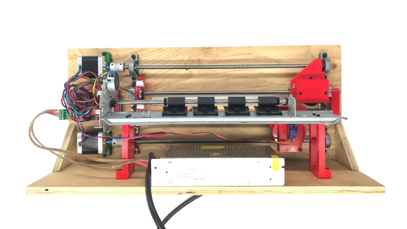
While other embossers forcibly punch the letters in one go, OpenBraille takes a more gradual approach to ensure a clean impression with a rolling motion. Paper is placed between a mechanical encoder with moving pins and a dimpled roller that provides resistance and a place to land. The embossing head is driven by an Arduino Mega and a standard RAMPS board, as the rest of the system relies on Cartesian movement.
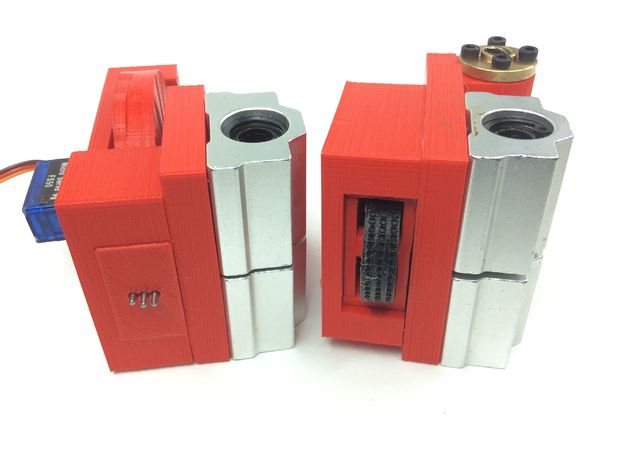
The encoder mechanism itself is pretty interesting. A micro servo drives a 3D printed wheel with three distinct tracks around half of the edge. The peaks and valleys encoded in these plastic tracks actuate the embossing pins, which are made from nails embedded through the sides of hex nuts. There’s a quick demo of the encoder movement after the break, and another video of it in action on the OpenBraille Facebook page.
[ccampos7] has all the files up on Thingiverse and plans to post the software soon. You should also check out this compact embosser that was recognized in the first round of the 2017 Hackaday Prize which is a nice all-print Braille concept.


That’s pretty cool. The guy in the video is right, normal braille embossers are loud as hell. I installed one in an elementary school and you could hear it printing pretty much everywhere in the school.
Cool project, interesting approach.
Thanks for posting.
Isn’t this something a low-powered laser cutter could do? Cut or burn out holes in a sheet of paper?
You don’t want holes, you want bumps that can easily be recognized by your fingertips. Patterns of holes are much more difficult to discern than patterns of bumps.
neat (cheap) approach to being able to move the pins without resorting to multiple servos for each detente although I think he missed a trick in encoding the 8 pin configurations (of the 3 pins).
He’s got his ‘encoder wheel’ (basically a stacked cam) done as a simple binary sequence which gives rise to multiple pins moving simultaneously during rotations (worse case is having to push two pins at once during 100->011), whereas if he’d done a gray-code, on each transition, the cam would only be changing a single pin at a time (reducing the stress on the encode wheel drive). Equally, given he’s only really using half of the encoder wheel rotation, he could have spaced them a bit more and offset each pin transition so the 100->011 actually goes via 010 for example – it just takes slightly longer to rotate to the next valid setting)
Those printers are expensive! I wonder if this could be made even cheaper or easier to reproduce if it wasn’t electrically driven, but instead the user would provide the input to feed the paper and move the printing head. There would probably have to be some kind of indexing, and the back and forth rolling motion of the print head would make it somewhat non-trivial. Then again, the current design isn’t all that complicated or expensive, and definitely faster than anything manually driven.
You don’t really need to stick to one a single pin moving at a time, as long as no two pins move in the same direction. A pin moving inward doesn’t take any torque, but considering you do need to encode 7 combinations anyway, you might as well use regular gray code. The “no pins” combination isn’t needed, because you could simply skip rolling instead.
You could try to reduce the wear on the wheel if you could use a clever arrangement of combinations, with each combination more than once on the wheel, and moving to one of the required positions with the smallest number of transitions on the way. Using a stepper instead of a servo might also help, because you can do full rotations that way, so you aren’t forced to go all the way around if you have to go from the first to the last one.
I’d be a bit concerned about the wear on the wheel pressing the pins, but that could always be improved in a next revision, if it really is a problem at all. Maybe a few small ball bearings underneath the pins, so they roll on the wheel instead of sliding.
I have to say, the rolling action is very clever!
There are many things to try. I am looking forward to hear ideas and to work with other makers to test them. I managed to put the machine together but I hadn’t work on optimisation and many other points. Thanks for the idea!
I remember seeing a video on diginfo or something like that about a Japanese guy who made a braille display that was easy to manufacture and low power and more importantly very small, they even showed it could be put in watches I think.
So what happens to such inventions? Do they just burn the paper or patent it in a way that nobody can ever use it or what?
It really annoys me seeing innovation like that being thrown away, and if it can really help people with a physical impairment it doubles the annoyance. But I see it on a regular basis.
Reminds me of that time Microsoft research showed a keyboard that was as cheap to make as rubber dome but where the switches were pressure sensitive, and what happens to that? Again destroyed by patent lockdown and the patent owner having no intention to give something to the world.
What about the metal sheet frame you have used? Is it from old printers? May I know make and model of the old printer used?