When it comes to production, fast is good! But right the first time is better. Anything that helps prevent rework down the line is worth investing in. Some of the best tools to catch problems are good test fixtures. The folks at Tertill (a solar-powered robot for killing weeds that kickstarted last year) took the time to share two brief videos of DIY test fixtures they use to test components before assembly.
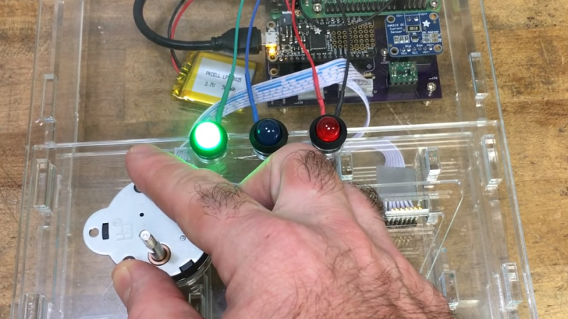
The videos are short, but they demonstrate all the things that make a good test: on the motor tester there are no connectors or wires to fiddle with, the test starts automatically, and there is clear feedback via prominent LEDs. The UI board tester also starts automatically and has unambiguous LED feedback, and sports a custom board holder with a recess just the right shape for the PCB. Once the board is in, the sled is pushed like a drawer to make contact with the test hardware and begin the test. The perfectly formed recesses in both units serve another function as well; they act as a go/no-go test for the physical shape of the components and contacts being tested.
Both videos are embedded below; and while there isn’t much detail on the actual test hardware, we do spy a Raspberry Pi and at least two Adafruit logos among other hacker-familiar elements like laser-cut acrylic, 3D printed plastic, pogo pins, and a PVC junction box.
Some of you may recall seeing Tertill as a prototype almost exactly a year ago. A year can be a long time, but as Amanda Wozniak said: a working prototype means that things are 15% done and the fun part is over. Thankfully, the OpenFixture project takes some of that hassle away by making it easy to design test fixtures around pogo pins.


It looks like a great deal of thought was put into this.
One critique: the motor tester has no way of knowing whether the motor is wired correctly or not, since it doesn’t detect the direction the motor is turning, so this relies on the operator visually verifying this, which is highly error prone. Wait – is it supposed to be CW then CCW, or the other way? Perhaps a cheap rotary encoder could be placed onto the motor’s shaft for this.
Better yet a laser and some sensors for that, when the flat on the shaft comes around it will shine the laser at one or the other first.