A couple years back we covered a very impressive transistor logic clock which was laid out so an observer could watch all of the counters doing their thing, complete with gratuitous blinkenlights. It had 777 transistors on 41 perfboards, and exactly zero crystals: the clock signal was extracted from the mains frequency of 50 Hz. It was obviously a labor of love and certainly looked impressive, but it wasn’t exactly the most practical timepiece we’d ever seen.
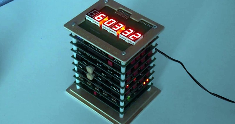
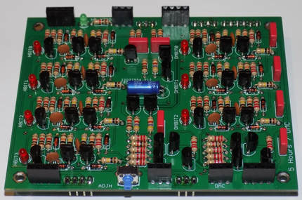 Creator [B Brett] recently wrote in to share news that the second version of his transistor logic clock has been completed, and we can confidently say it’s a triumph. He’s dropped the 41 perfboards in favor of 9 professionally fabricated PCBs, which this time around are stacked vertically to make it a bit more desktop friendly. The end goal of a transistor logic clock that you can take apart to study is the same, but this “MkII” as he calls it is a far more refined version of the concept.
In addition to using fewer boards, the new MkII design cuts the logic down to only 283 transistors. This is thanks in part to the fact that he allowed himself the luxury of including an oscillator this time. The clock uses a standard watch crystal at 32.768 KHz, the output of which is converted into a square wave through a Schmitt trigger. This is then fed into a divider higher up the stack which uses flip flops to produce 1Hz and 2Hz signals for use throughout the rest of the clock.
In addition to the original version of this project, we’ve also seen a beautiful single-board wall mounted version, and even a “dead bug” style one built from scraps.


This would make an excellent Tindie kit
Oh yes, that would be very nice, I would buy it.
Meh. I liked the original better. Maybe it wouldn’t fit on a desktop, but it made a fantastic wall clock. This one? Not enough blinkenleitz, and not enough components visible. I can see it if he wants to be able to sell kits, or even finished clocks, since the pricing would have to be way too high for the perfboards, but this is just too generic for my taste.
Why did the step from 50Hz line sync to crystal control reduce the number of transistors? >ou need 15 divider stages from 32kHz to 1Hz but only about 6 from 50Hz to 1Hz.
Still too many transistors, there’s no need for full decoding and buffering every stage. I built such a monster including xtal clock source and blinkenlights a decade ago using approx. 130 transistors and 350 diodes (and a lot of inspiration from ancient literature).
I was looking at a weird one the other day, seem to use reverse biased FETs to chop charge capacitors, was for 60hz so had 10:1 and 6:1 stages that used 1 transistor each. I didn’t brain it fully it was an ancient design and couldn’t figure if it was finessing some secondary characteristic (i.e. usually undesirable bug) of particular components or not..
Yes. I’ve seen this in ancient military radar systems, where every active device cost $$$. The circuit charges a capacitor a certain amount with each incoming pulse, and triggers and discharges the capacitor once a threshold is reached. 5:1 or 6:1 should be no problem with this type of circuit, but 10:1 is kind of asking for it – it can easily trigger on the 9th or the 11th pulse just from variations in components. On one system, which was fully vacuum tube technology, this was done with a single pentode, but I don’t remember if the one I saw that used (germanium) transistors managed to do it with only one. This was used to generate range rings on the radar display, which typically were in 10 mile increments, and every fifth one was intensified, thus the need for a 5:1 counter.
Ah thanks.. that’s what it looked like it was doing but I wasn’t quite believing it, as you say component factors and temperature variation could have had it miscounting. I was thinking I was missing some subtle phase locking or something. The brief note with it didn’t even mention component tolerance, but there were variable potentiometers in each stage to fudge*cough* calibrate it. Seems likely it might have been derived from an older vacuum tube circuit since FETs are supposed to be an easier substitution for such.
All I can say is NICE. It is good to see people doing this sort of stuff (going back to basics), and doing it so neatly/professionally.