When you think of a software defined radio (SDR) setup, maybe you imagine an IC or two, maybe feeding a computer. You probably don’t think of a vacuum tube. [Mirko Pavleski] built a one-tube shortwave SDR using some instructions from [Burkhard Kainka] which are in German, but Google Translate is good enough if you want to duplicate his feat. You can see a video of [Mirko’s] creation, below.
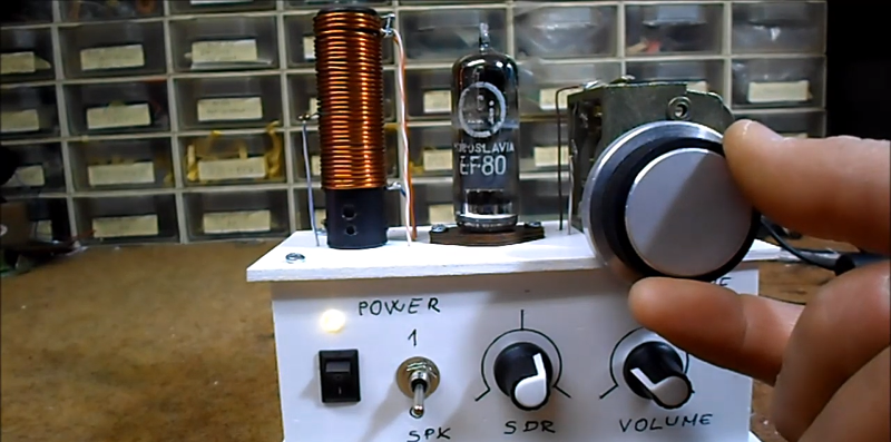
The build was an experiment to see if a tube receiver could be stable enough to receive digital shortwave radio broadcasts. To avoid AC line hum, the radio is battery operated and while the original uses an EL95 tube, [Mirko] used an EF80.
To get the necessary stability, it is important that everything is secured. The original build made sure the tube would not move during operation, although [Mirko’s] tube mounting looks more conventional but still quite secure. Loose coupling of the antenna also contributes to stability, and the tuning adjustments ought to have longer shafts to minimize hand capacitance near the tuning knob. Another builder [Karl Schwab] notes that only about 1/3 of the tuning range is usable, so a reduction gear on the capacitor would also be welcome.
The tube acts as both an oscillator and mixer, so the receiver is a type of direct conversion receiver. The tube’s filament draws about 200 mA, so battery operation is feasible.
According to [Burkhard] his build drifts less than 1 Hz per minute, which isn’t bad. As you can see in the video, it works well enough. The EF80, by the way, is essentially an EF50 with a different base — that tube helped win World War II. If you like to build everything, maybe you could try the same feat with a homemade tube.


Yugoslavia still lives!
In EF80 at least …
So audio is fed to the sound card, I presume? And anode voltage only 6 V?
No, it’s not a SDR, but a superregenerative converter. They’re very sensitive because they’re right on the edge of oscillation. You can demodulate AM and FM, and pretty much anything else that’s not CW gets downconverted to baseband. Transistors work in these circuits, too. I built one with a 6U8 in, um, around 1964ish that pulled in FM broadcast.
The downside is that they oscillate, and radiate out the antenna.
Boy, if I had a nickel for every time I radiated out my antenna I’d be a rich man.
If you radiated too much power without a license or in the wrong band, you’d be a poor man.
I’ve done about 300KW, but all legal.
Agreed. Perhaps “SDR” on the pot translates to “regeneration” or something like it in German?
“Perhaps “SDR” on the pot translates to “regeneration” or something like it in German?”
Um… I used to smoke a lot… oh wait… I didn’t inhale though… yeah… that’s right… vape and juicing technically towards the end actually. Seriously… takes a lot to juice.
The great God of Definitions other than Google Definition declares in the latest revision in U.S. English that the system is a SDR.
Google “sdr defintion” keeps returning “Special drawing rights (ISO 4217 currency code XDR (numeric: 960), also abbreviated SDR) are supplementary foreign-exchange reserve assets defined and maintained by the International Monetary Fund (IMF)…” blah blah blah
https://en.wikipedia.org/wiki/Software-defined_radio
“Software-defined radio (SDR) is a radio communication system where components that have been traditionally implemented in hardware (e.g. mixers, filters, amplifiers, modulators/demodulators, detectors, etc.) are instead implemented by means of software on a personal computer or embedded system.[1] While the concept of SDR is not new, the rapidly evolving capabilities of digital electronics render practical many processes which were once only theoretically possible.
A basic SDR system may consist of a personal computer equipped with a sound card, or other analog-to-digital converter, preceded by some form of RF front end. “
So the answer is no. It is not a software defined radio.
With this definition:
“SDR can be defined as a wireless communication device where the receiver and transmitter functionality is changed or modified by software without making any physical changes to the hardware.”
http://mil-embedded.com/articles/software-defined-radio-key-seamless-effective-military-communication/
Mein Deutsch ist nicht so gut.
The SDR pot is the 22K that biases the screen grid, and the tube is run at zero bias and low plate voltage. Kind of the wrong way to run a beam power pentode, but maybe they just had one and fooled with it until they got it to work as an oscillator. The “SDR” control doesn’t seem to do that much but control the regeneration through current control.
Maybe a more Puritan holistic SDR upgrade would be the addition of digital pot?
https://makezine.com/projects/make-43/digital-potentiometers/
I didn’t know if there are digital caps… looks like there are without having to add motors.
https://www.mouser.com/datasheet/2/205/NCD2100-515357.pdf
Then for some inspiration to roll or looks like with expansion capabilities to add capacity or wait… that wasn’t the pun intended since this example would be inductance… grow your own in this way:
https://www.amazon.com/Electronics-Salon-1000uH-Standard-Programmable-Inductor/dp/B00UT07B9E
However… for the puritans old school… suppose the hand dials can have an all “SDR” option for controls.
Thanks… this was an interesting example and study to computer control more… or wait… software define more.
He is feeding the output to digital demodulation which is why the stability is such a concern.
Neat build! Cool… Mr. Carlson Lab just posted a video with some great details that might help inspire an AC line version of this or other AC build to be less noisy since he goes into design details… though battery op is the best way to go to reduce noise from what I can tell.
https://www.youtube.com/watch?v=uGXQc-zanWg
Someday people will “reverse engineer” SDR and be amazed they can make a radio with linear amplifiers, a very primitive radio compared to what SDR can do. Regen was everyone’s first radio in the old days. Well, after a crystal set. http://www.analogdial.com/KT135/KT1351.html
Heh. Wonder if I can pull off the same trick with two “vacuum tube indicators” ? I did manage to hack one using modwire and micro-solder, looks like one type can be made into a tetrode if you don’t care too much about stability.
It certainly does change the bar appearance a bit when I connect the “extra” pins to +V or Gnd though try not to apply over-current to the heater or bad things happen. Laser cut the support via Bluray diode maybe to add the extra physical grid?
Best to add a series limiter ideally, a good method is to use a small lightbulb such as grain of wheat indicator
as these are somewhat more fragile than the heater and blow first!
A PC is used to decode DRM (Digital Radio Mondiale) by sampling the radio’s baseband output with a sound card, but this is just a conventional radio with analog mixer, oscillator etc – not “software defined” at all.
For those who are not European: https://en.m.wikipedia.org/wiki/Digital_Radio_Mondiale
Hackaday used to be good. Now it’s just low effort posts..
ŝi parolas Esperanton per radio <3