Analogue TV signals are a beautiful exercise in order and synchronisation, in that as the white dot on your old CRT TV back in the day traced its way across the glass it would have been doing so in faithful obedience to the corresponding electron beam in the camera at the studio. But a camera with a lens and light-sensitive scanning camera tube wouldn’t have been the only way of generating a picture. The flying-spot scanner drew a raster over its subject — usually celluloid film — with a white dot of light and recorded the result with a single photocell to produce a video signal. The ever resourceful [Niklas Roy] has built one using a video projector.
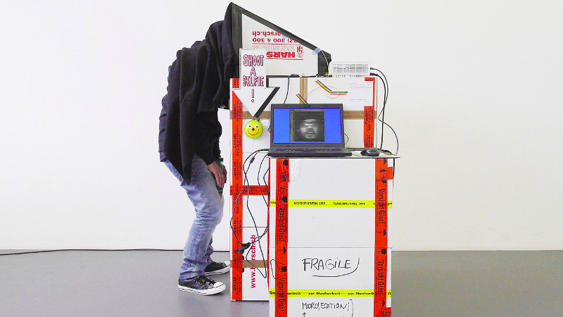
In this scanner the “dot” is a square of white pixels that is moved around the scene, while the sensor is a photoresistor that is read by an Arduino which passes the data to a PC. The whole is mounted in a booth that the subject positions themselves in front of, and covers their head with a cloth. It’s a slow process because the photoresistor is hardly the best sensor, in fact a portrait takes 83 seconds.
The result is hardly superlative quality, but of course this is an artwork in itself rather than a particularly good camera. It is however an impressive piece of work, and we know we’d give it a go if we had the chance.
[Niklas] is a frequent feature on these pages, having produces some pretty impressive work over the years. Some of our favourites are his container-sized music construction machine, and his tiny cardboard plotter.


Overkill… Needs a Nipkow disk!
A Nipkow Disk would at least speed the process up! Because the limiting factor when it comes to speed is not the LDR, as stated in the article, but the frame rate of the projector. However, a better photo sensor would probably help to reduce the noise and it would be better suited to capture color images.
Back in the day, synchronizing the disks at both ends of the transmission was a tricky thing. I read a book about TV printed back then, and it described how the viewer could ride a rheostat to keep the disks in synch. The same book also said that there was no future in CRTs…
It would be interesting seeing a modern approach to synchronizing the disks…
Would probably something like a PLL. Phase synchronization for grid connected generators/backup battery systems use a PLL to align inverter phase before connection. PLLs are a robust, well understood method and can easily be implemented in both analog or digital systems and both discrete or integrated techniques.
You add a frame pulse to the signal for the blanking interval every revolution and then basically do the same thing as with analog servos. Pulse comes in, gets XORed with the same pulse generated by the local disc, and that generates a variable width second pulse that measures the overlap of the two.
You basically get a single pulse for every revolution that kicks the motor running the disc along, and the pulse width varies depending on how much the two overlap. When the receiver’s disc starts to lag behind, the pulse width increases and makes it faster. Eventually the two synchronize with a constant phase shift, which can be zeroed out by shifting the local pulse phase.
I really like this idea.
It turns out to be quite simple. The entire electrical grid is in sync with itself, so just use synchronous motors on both sides, and add a way to add an offset to the receiving disk.
Group I fax worked this way (from the early days of fax, well before they went digital). There were no sync pulses and PLLs, just synchronous motors. If you recorded a Group I fax signal and played it back on another day, the image would be skewed, since the frequency of the grid changes (but also interestingly, is more accurate than a crystal timepiece over the course of months but that’s another story).
Have you thought of trying the full-screen patterns used in structured light 3D scanning? The math for getting the image from the values returned by the sensor would be more complex, but it could speed things up quite a bit…
Yes, I spend quite a bit of thought into it and also experimented with it. In my understanding, the useful part of structured light for 3D scanning are basically the borders between the black and white areas. In a typical sequence of structured light patterns, each image is half black and half white and the resolution of the structure doubles with every new image. This sequence of patterns is useful for capturing the 3D surface of an object with the 2D sensor of a camera but its quite useless for taking a photo with a single photo cell.
The reason is that always half of the image area is illuminated and its brightness is reflected back into the sensor. In practice it means that the the captured luminosity is always roughly the same for each of the projected patterns.
“Roughly the same” isn’t the same as “exactly the same” :D The image data has to be there somewhere; it’s just a matter of getting it out…
My thinking was that if you draw rectangles of the luminosity returned by the sensor (possibly weighted by how many total patterns there are) and multiplicatively combine them over the area(s) of the output image corresponding to where the light falls, it would build up an image. Each pattern would have to have an inverted version (e.g. left half white, then right half white), and you’d have to do horizontal and vertical separately and combine them, but I think it should work.
I have a small but very bright 800×480 pocket projector, so I may give this a shot at some point (double pun intended).
Colored spots and gels over (multiple) SDRs? Or simply faster light sensors?
But honestly, the project is perfect as-is. The point is not ekeing out maximal performance, right?
I still haven’t gotten around to trying this, but I don’t think the fact that the edges are used in 3D scanning means that there isn’t value in using this for your purpose. It won’t have roughly the same luminosity every time, because the luminosity returned by the sensor will only represent what bounces off the lit parts of the scene, just like with the flying spot. I’m thinking it would go something like: For each pattern projected, draw rectangle(s) with the luminosity returned from the sensor in the same place(s) the pattern has white (or red, green, or blue, if doing color separation). Once you have all the generated patterns (for both axes and in all primaries), combine (average?) them. If you get the math for combining them right, the result should represent the actual luminosity returned from the object.
This is a nice project, an ode to the systems of the past by using an overkill of modern technology to achieve the same goal. A wonderful idea to cellebrate the marvelous minds of a century ago.
You may thnk that the slow scanning of the system is a disadvantage, but actually the slow scanning does add to the appeal as it very clearly shows how it works.
If it used a real flying spot (not a crawling spot like here) then you wouldn’t notice the scanning principle.
NBTV.org has lots of interesting information, I built a televisor using their circuit boards, the video is converted to audio (weird concept listening to a picture) and bingo a tiny but surprisingly good image.
Did anyone manage to build a cheap and easy to reproduce mirror screw yet? Those things seem fun to play with, but so difficult to come by or make.