If you have done any sort of radio work you probably have a fair idea about what antennas do. It is pretty easy to have a cursory understanding of them, too. You probably know there’s something magic about antennas that are a quarter wave long or a half wave long and other multiples. But do you know why that matters? Do you understand the physics of why wire in a special configuration will cause signals to propagate through space? [Learn Engineering] does, and their new video is one of the best graphical explanations of what’s really going on in an antenna that we’ve seen. You can watch the video below.
If you tackle antennas using math, it is a long discussion. However, this video is about 8 minutes long and uses some great graphics to show how moving charges can produce a propagating electromagnetic field.
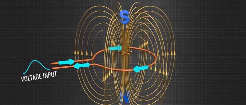
The 8 minute time limit did however leave us wanting more, as the first part does a great job of explaining charge movement in a dipole but what follows just looks very quickly at some TV, satellite, and cell phone antennas.
This video won’t make you an antenna design expert, but unless you are a guru we will bet you find at least one thing you didn’t know in them. If you want to go further, [Mark Hughes’] introduction has graphics that aren’t quite as slick as these, but still make for a much easier explanation than you’ll find in a textbook. If you do go all in on antennas, modeling them is easier than it used to be, thanks of course to computers.


“If you tackle antennas using math, it is a long discussion. However, this video is about 8 minutes long and uses some great graphics to show how moving charges can produce a propagating electronic field.”
Back when Flash and JLNP was a thing there where interactive examples online.
Why antenna ends are open circuited… Even though it is able to produce magnetic field in closed circuit..?
As an antenna engineer I can happily endorse this message. Great video.
Errata. When receiving the wave front is normally flat rather than tightly curved in the transmit case. Also the electrons don’t actually travel the entire length of the wire as the animation shows, but the end result is the same.
Exactly. Would’ve made a nice intro to the topic in our E&M course.
Question: explain the monopole antenna?
The ground plane beneath the antenna acts as a mirror, I understand, but how does it interact to make the wire sticking out of the plane like a dipole antenna?
Image theory – check out:
https://en.m.wikipedia.org/wiki/Image_antenna
monopole antennas dont’t exist. Think ofcharge conservation.
The best way to imagine what is going on is to consider placing a burning 4 to 6 inch candle on a 1 foot square mirrored tile. (You can use a tea-Light, but you should use a much smaller mirrored tile—maybe a coaster).
Now move your field of vision until you can see two flames—the original, and the reflected.
At this angle you have twice the output power of the ‘real’ candle. Now move your field of vision until you can only see one flame (the original). You have just discovered a portion of the pattern boundary of your antenna model.
That is how a counterpoise works.
Think of a dipole as a very rapidly changing magnet with a North and South pole that alternate very quickly. On a vertical dipole, the bottom element serves to provide an opposite or counterpoise to the varying electrostatic and electromagnetic fields across the upper and lower elements. If you put a ground plane at the centerpoint where the antenna is fed, typically with an unbalanced feed, currents and voltages are induced in the ground plane which approximate what would be present at that location from the standing wave created by the counterpoise element. The ground plane is useful for creating a standard pattern approximating a dipole, but is in no way necessary to radiate RF. As mentioned, it approximates the pattern, but in reality it isn’t equivalent. Consider an elevated ground plane antenna with a sufficiently large ground plane elevated a couple of hundred feet above ground. Because of the lack of a radiating counterpoise element, the radiation pattern below the antenna center point horizon is almost non-existent, which is very different from the toroidal pattern created by the dipole. Radiating elements without a counterpoise? Ham radio guys do it all the time. It’s called a longwire antenna.
Haha, saw it a couple of days ago and thought: hmm, maybe its a video for hackaday…. naaah
Great to see it here, it really helped me to FINALLY understand the concept..
“moving charges can produce a propagating electronic field” A what now? Could it be that the word you are searching for is “electromagnetic field”? :P
Finger memory… fixed
I love that hackaday is my most grammatically correct source of news!
The video has two misspelled words.
I see the video uses the old “electrons piling up at the end of the wire” idea to explain propagation. Is this idea not fundamentally false? Does this not call into question the rest of the video’s content?
Yes, it’s false.
The only way to really understand antenna is in terms of boundary value problems for the 3d wave equation.
See “Partial Differential Equations” by Aaron Sommerfeld, which does it nicely.
@penny et.al. “See “Partial Differential Equations” by Aaron Sommerfeld, which does it nicely.”
Any other graphical representations online you’re aware of to explain? Graphical representation of any mathematical logic and physical phenomena is a must for me to grasp the detail and lock in to long term memory.
Not finding a copy of the textbook or paper unless is this Quarterly of Applied Mathematics Vol. 10, No. 2 (July, 1952), p. 193 “Partial Differential Equations” by Arnold Sommerfeld: https://www.jstor.org/stable/43633950?seq=1
It’s part of Sommerfeld’s series on mathematical physics–try google books.
I think it probably is the book that you found reviewed.
It might be a Dover book by now.
I don’t know any online graphical representation, but try looking for one on the 3d wave equation and its boundary value problems. I don’t find graphical representations very useful myself. They tend to be full of lies and confusion.
However, using Sommerfeld’s formulae, one could plot the solutions in Mathematica (useful sliders) of
Matlab. That would work well. The wave equation is linear, the solutions are explicit and this makes them easy to plot.
“Sommerfeld’s series on mathematical physics… …might be a Dover book…”
Thinking this is the book: https://www.abebooks.com/Partial-Differential-Equations-Physics-Lectures-Theoretical/30582289412/bd
Looks like this is the 4th printing: https://archive.org/details/in.ernet.dli.2015.469819/page/n11/mode/2up
“I don’t find graphical representations very useful myself. They tend to be full of lies and confusion.”
I think I get what you are saying, i.e. when the graphical representation of a system is by a graphics artists and not a scientist or engineer.
I know if not for Logo maybe first or with BASIC with the TI-99/4A rather crude (I don’t recall conceptualizing the math though really well then… was more a plug and chug act), then undoubtedly the TI-83, then TI-92, then EXCEL (I know, not so accurate) and later MATLAB… I totally wouldn’t be able to visualize math so well in regards to what I can.
I haven’t used Maple or Mathematica since I had physics in the late 90’s and only used briefly since I was able to most with the calculators. Will have to see what R can do now days and I did just install Octave I think with the QucsStudio. I recall Octave being an open source MATLAB equivalent… so will read into next since might be a good video to make also since can be made with the screen recorder.
I still need to read into the 3D simulations apps more as I’m just learning LTspiceIV, MicroCap12 and QucsStudio (the later seems really impressive)… though seems like CST Studio and maybe some other applications can perform an artistic graphical representation more mathematically accurate/precise?
https://en.wikipedia.org/wiki/Simulia_(company)#CST_Studio_Suite
I’ve downloaded a student edition of CST Studio… though am still early on in my studies and haven’t used yet. Thinking time to read into Octave and try some examples then plug and chug some data into equations.
I read into a tangent with a related application after reading the article “A Practical Look at Chokes for EMI Control” then “Real World RF Design and Filter Construction” and the comment section of the later article had a reference to OpenEMS.
Hackaday happens to have an article on OpenEMS too. https://hackaday.com/2017/07/28/openems-makes-electromagnetic-field-solving-merely-difficult/
Looks like instead of jumping into CST Studio; there are some other open source options, that might be useful I see after reading in the comments, that might demonstrate the phenomena better:
http://openems.de/index.php/Tutorials (OpenEMS)
http://onelab.info/wiki/ONELAB (ONELAB)
https://www.qsl.net/4nec2/ (4NEC2)
This comment has some good references to read into also thinking to have referenced here for more detail for others. https://hackaday.com/2017/07/28/openems-makes-electromagnetic-field-solving-merely-difficult/#comment-3809495
My feelings about this video are mixed.
The statement (after 2:50) “It is interesting to know that the wavelength of propagation so produced is exactly double that the length of the dipole” may be misleading. This suggests that the wavelenght is dependent on the length of the antenna, which is of course nonsense (the wavelength is speed of light/frequency). Of course lambda/2 antennas are efficient. However radio amateurs somtimes use longer antennas. And think of an atom or molecule emitting light: the antenna (essentially the size of the atom or molecule) is much smaller than the wavelength( an by the way: an emission with 100% efficiency!).
Next: 4:36: the field which acts on a receiving antenna is usually not a time-reversed copy of the radiating field. Most antennas are excited by plane waves. Of course there is a so called reciprocity theorem. And a plane wave can be expressed by a multipole expansion in multipole waves. The same about the wave holds for the LNBC (after 6:35).
The LNBC has two probes: ” .. the available spectrum can be used twice”. Spectrum? Twice? This has nothing to do with a spectrum. The two probes are used to receive horizontal and vertical polarized waves, and, because the distance between them is a quarter wavelength, to receive efficiently either right handed circular polarization (RHCP) oder left handed circular polarization (LHCP).
Longer antennas have the same effect; they still need to be n times the 1/2 wavelength. The point is that you need to form a standing wave inside the antenna (at the propagation speed inside the metal, not free air). How many nodes of a standing wave you have is unimportant, although longer antennas have a different radiation pattern than simple 1/2 wave dipoles.
They’re simply pointing out the natural frequency of the antenna. “So produced” refers to the fact, because only the natural frequency would form the standing wave they’re describing.
Hello
what is the ‘propagation speed inside the metal’? (e.g. for alumina)
Thanks!
Is that Velocity Factor? Felix wrote about that: https://lowpowerlab.com/guide/rf-best-practices/velocity-factor/
Not really. Most AM towers are 5/8 wavelengths. Cop car antennas are quarter wavelength and there are many more. Non directional beacon antennas for airports are about 30 feet tall where the wavelength is about 1/2 Km. and they have a range of about 60 miles with 10 watts. The 1/2 wave, 1/4 wave, wavelength multiple, etc. is not a necessity but a way of easily matching impedance to a power source.
Propagation velocity on a dipole rod is somewhere in the 95% range but it isn’t generally calculated. The velocity of propagation makes the antenna rod physically shorter than the wavelength fraction. An antenna is tuned with a network analyzer for maximum return loss with adjusting the dipole length.
Hope you do realize that 1/4 * lambda is the same as 0.5 * lambda/2, yes?
And 5/8 * lambda is merely 5/4 * lambda/2, yes?
Funny
Yes you can use the vertical and horizontal polarizations or left hand and right hand circular polarization for completely separate signals. It is a common practice with high end point to point microwave systems and the way VSATs reject adjacent satellite signals ( adjacent satellites alternate polarizations on co-channel signals). The polarization discrimination is around 20 dB (100:1) to 30 dB (1000:1) and depending on your required Eb/No or C/SN ratio is generally enough to support 2 independent paths on the same frequency.
After coming across the concept of an ‘Evolved Antenna’ –
https://en.wikipedia.org/wiki/Evolved_antenna
I’ve wondered what else might similarly benefit from this ‘Darwinistic’ methodology ?
Lots of things, it turns out–you may want to have a look at John Koza’s work: http://www.genetic-programming.org
I’m really not a fan at all of the first video because it is mostly based on erroneous statements. I wonder where to start…
First off, the assumption that hooking up a loop and getting a magnetic RF field doesn’t work for transmission or reception is completely wrong.
There is no efficiency difference between a slot antenna which gets its radiation from current flow around a metal loop vs a dipole which appears to radiate based on voltage on counterpoised rods.
Some quarter million dollar TV broadcast slotted array antennas are based on inductive radiation (to get horizontal E field polarization from a vertical pipe structure), almost every AM radio works with a loop (coil) antenna wrapped around a ferrite core and one of the most popular ham antennas is an inductive Halo.
Radio waves consist of equal measures of electrostatic field and electromagnetic field components and the video completely ignores that.
There seems to be much made of the dipole and radiated frequency but there is nothing special about a dipole and it isn’t needed for efficient RF, it is just convenient as a pattern reference and a dipole with 2 quarter wave elements is convenient as a one of the choices for a minimal radiator that has non reactive coupling to radiate.
The video focusses on electrostatic radiation but completely missed that both voltage and current elements occur to create the radio wave.
The video showing the ” radio bubbles” and the shape from a voltage disturbance and the comment that the shape is based on a “memory” the radio wave has is completely wrong. If you’ve watched this you probably should unlearn this.
Although it is a noble quest to try to visualize what is going on within the near field of an antenna, the real answer is that it is unorganized combination of electrostatic (E field) and electromagnetic (H field) that is very easily disturbed and if attempted to be measured change their characteristics. If you put 2 resonant dipoles adjacent to each other in the near field they take on the attributes of a transformer with mutual coupling and almost completely quit radiating at a distance. The “flatness” of the pattern is probably more about the propagation delay of the radiated wave and the distance to the center of the rod dipole element. There is no “memory effect” of radio waves. There is no “flatness” or pattern delay in the far field where all radiating components combine to create a plane wave from a point source.
There are numerous other glaring statements and theories in the video. I’d just say skipping it altogether and not having to unsee things.
The other videos are excellent, but maybe send the first one back to rewrite. (and maybe spell check)
+1
Isn’t that capacitance?
I ma wondering how you do your animation… really cool…