If you’re testing a power supply or battery pack, an electronic load is a nice tool to have. By watching the voltage as you crank up the resistance, you can verify the unit’s real-world capabilities quickly and easily. But [Xavier Bourlot] wanted a bit more information than is generally afforded by these devices, so he came up with his own scratch built load that can measure the voltage at multiple points in the circuit.
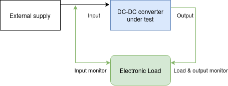 Now at first glance, it might not be obvious why you’d want such a capability. But [Xavier] is looking to do something very specific with this device: analyze the efficiency of DC-DC converters. The idea is that if the electronic load can measure the voltage on both sides of the converter, it can calculate what kind of losses are being incurred.
Could you do this with a multimeter and a traditional electronic load? Sure. But if it’s the kind of thing you’ll be doing a lot of, it’s not hard to see why this method would be preferable.
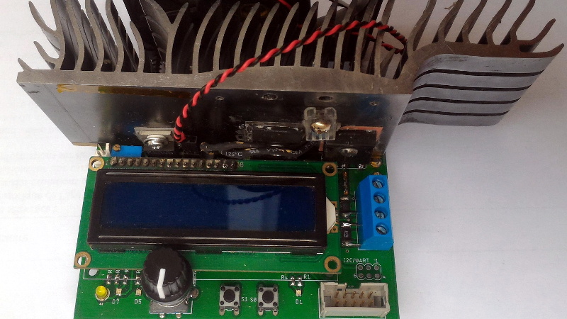
But even if you ignore the converter analysis capabilities, this looks to be a very useful device to have around the lab. [Xavier] says it can sink more than 5 amps, and handle an input voltage as high as 100 volts. Powered by an ATmega328P, the load is also fully programmable and even features an I2C expansion port that you can use to hang additional hardware or sensors on. The stock firmware is already quite capable, and the list of future enhancements has some very interesting entries such as the ability to log data over serial or to a SD card.
We’ve seen a number of programmable electronic load projects over the years, ranging from Arduino shields to VFD equipped units that would be the pride of any hacker’s bench.


That heatsink!
“Could you do this with a multimeter and a traditional electronic load?”
Well, if you’ve got a proper bench supply with current limiting (and therefore current monitoring), you don’t even need the multimeter, just an interface to both of them.
But it’s a pretty smart addition anyway, most simple electronic loads have tons of leftover analog inputs, might as well put them to use.
Wouldn’t it be “crank down the resistance?”
Boy HAD is not doing well today. Must have had a hard party last night. They probably meant “crank up the current,” of course.
I’d actually be mildly interested in how a voltage source performs with high resistance. Some sources require a minimum load to regulate properly.
Nice Ge force heatsink, nice project
Heh, yes, I’ve got one of those with the GT710 still attached to it.
Actually the analog acquisition is done by the LTC2992, which features 12bit current and voltage resolution, way better than your average 10bit atmega ADC.
You could use the venerable bme280 on the i2c bus to measure the temperature of the load over its input range. I could totally use a device like that to measure the performance of dc to dc regulators.
Cool trick if you need a test load of fixed value: measure a length of enameled copper wire so that it has the right resistance, and submerge it in a bucket of cold water.
Hot components can affect the accuracy of your measurement circuits eg. voltage reference, ADC (offset/linearity etc), opamp (offset), voltage divider (tempco), current sampling…
I would rather have separate PCB(/DMM) if I want accurate results. As is, the results won’t be useful.
If you keep the hot load separate from the control PCB, you could also upgrade the load with a higher capacity version while still using the same controller.
As is, the load stay within the +/-5mA spec over a temperature span of 20 to 75°C, so not that bad. The voltage reading suffers a bit more however