It seems like every year, it gets a bit easier to build your own CNC. From the Enhanced Machine Controller (EMC) project of the early 1990s to Arduinos running Grbl in the late 2000s, the open source community has moved ahead in leaps and bounds. Grbl is at its core firmware that interprets G-code and commands stepper motors, 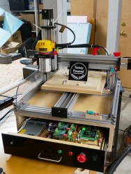 usually to move a tool head in such a way as to make something. Tons of systems have been built around it, including early Makerbot printers.
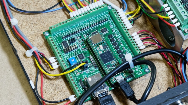
Its also spawned a plethora of other projects (the Grbl GitHib repo has 2,400 forks!), including a 32-bit flavor called grblHAL. This version is at the heart of a fantastic CNC controller board developed by [Phill Barrett]. Ditching the Arduino for a more powerful Teensy 4.1, [Phil]’s controller supports full five-axis control, variable frequency drive spindles, dust extractor control, and flood and mist coolant control. It can run at blazing stepping rates of up to 160 kHz (standard Grbl on an Arduino hits 30 kHz) and can be assembled with either a USB or Ethernet interface.
There’s no shortage of interesting Grbl-based machines out there — including a revamped Atari plotter and a three-axis rotary CNC (shameless plug for the author’s own project) but it’s always exciting to see new hardware developed that will undoubtedly find its way into the next generation of a family of projects. We can’t wait to see what comes next!


Why hasn’t Arduino come out with an actually official and faster unit yet exactly? The ARM Cortex-M7 processor at 600 MHz isn’t too shabby or expensive either.
They have. The Due’, MKRZERO and others. Unfortunately they didn’t take off like the ATMega designs. I could philosophize why but it doesn’t reall ymatter..
Teensy is definitely not an Arduino – it is way better.
Arduino Due
Flash Memory = 512 KB all available for the user applications
SRAM = 96 KB (two banks: 64KB and 32KB)
Clock Speed = 84 MHz
84 MHz vs 600 MHz isn’t exactly faster or better. I guess it’s 32 bit and better than the MEGA 2560 but it’s almost 2021 now. Let’s also look at the Raspberry Pi 4. It’s something like $30 or $40 and materially better in many ways. It isn’t a real time board like Arduino is but my point is that Arduino hasn’t exactly made much headway in the last 6+ years with regards to an actually faster and more technologically advanced board. That’s all.
The Grand Central M4 Express with the SAMD51
Cortex M4 core running at 120 MHz
1MB flash, 256 KB RAM
Is at least fairly decent but that too isn’t even an official board!
Also agree with you about the Teensy being way better.
https://forum.pjrc.com/coremark_barchart.png
1024K RAM (512K is tightly coupled)
2048K Flash (64K reserved for recovery & EEPROM emulation)
There is also the Portenta H7, which is an official Arduino product.
https://store.arduino.cc/usa/portenta-h7
Portentia is pretty cool but it’s amazingly pricey. Bang for the buck? The little 600 MHz Tensy 4.0 for $20.
It’s mainly because the ARM processors are a bitch and a half to program compared to the AVRs, and the Arduino libraries hide away so much of the low level stuff that you can’t really take advantage of it, and the libraries are buggy so you get mysterious faults and crashes, and the Arduino defaults aren’t nearly always sane – for example initializing all the output buffers on in an ATSAMD21 which makes the board not sleep properly.
For all it’s worth, as an “Arduino”, a 48 MHz ARM is just as fast as a 16 MHz AVR because of all the internal bus synchronization delays and flash wait states. You have to go really low level to actually make it do what it’s supposed to do, and that requires you to go straight in the deep end. For someone who’s just learning embedded programming, it’s practically impossible.
Umm… No. The ARM Teensies are just as easy to program as the Arduinos using Teensyduino. Same libraries, pretty much most Arduino code will run on a Teensy with no changes. And there are a lot of other processors that can be programmed through the Arduino IDE using the ported Arduino libraries.
Also, the various benchmarks out there don’t agree with your performance comments.
Any thoughts to adding connectors to match those common on Mach3/4 hardware (e.g. Ethernet Smoothstepper)? Would love to replace an ESS and bid farewell to Mach 4 in my Avid router.
What specific connectors would you like? I am looking to do a version with euro-style pluggable screw terminals. They are easier to use but cost more.
The ESS has 3 2×13 headers (and a 2×8 header) that allow for the use of a IDC ribbon cables to interconnect the control signals to a set of stepper drivers and other inputs/outputs (https://warp9td.com/index.php/component/content/article/14-sample-data-articles/125-what-is-a-motion-controller). Note the pin numbers on the 2×13 are not the “conventional” scheme. The DB25 pinout seems to be based on the historical connections used by MACH3. The Gecko G540 (https://www.geckodrive.com/support/g540-rev-8.html) pinout shows what seems to be the “standard”. In the case of a CNC router with limit sensors, VFD control, touch plate, coolant control, 2 of the 2×13 connectors are used.
I want more details about this machine.
What are those drivers?
Have a look here: https://www.grbl.org/projects
That’s my machine. Those are TB6600 from about 3 years ago. They work ok for under 3A. Note that the “TB6600” drivers you can buy these days are actually not TB6600s. I did a teardown here https://www.grbl.org/single-post/tb6600-fake-or-not-but-who-cares You can tell because the real TB6600 doesn’t support 32:1 microstepping and these all have it.
What stepper motor even steps at 160 kHz? You take 16 microsteps and it goes 10 kHz per actual step, which for a typical 200 step motor is 3,000 RPM. Most motors I know are lucky to get 500 RPM without losing all their torque.
closed loop hybrid stepper can run close to these speeds. But grbl and al are not really meant to use with them, at least you need an input per drive to monitor the fault output of the driver.
Sure, motors can run that fast, even ordinary stepper motors. They will have a reduced torque, but this depends also on the supply voltage. You need high supply voltages like 24V or better 48V to allow the driver to push the required current through the motor at high frequencies. Also, too high accelerations might cause stalls when trying to get to higher frequencies. In addition, higher microsteps also help, 16 is quite low. My combined 3D printer and CNC mill is running its motors at 900 RPM easily (at 32 microsteps), and the limit is only the slow 8 bit AVR MCU…
Plus at some point you will hit motor resonances that mess up the stepping entirely, and the rotational energy grows quadratically so the motor no longer responds to step changes and you start losing steps in trying to accelerate further, so it’s pretty much moot whether you can go that fast because it has no useful point.
Resonances do not occur for high speeds. They happen if the requested motion pattern excites a resonance of the mechanical system. That can be avoided by avoiding those frequencies. Truly advanced motion controllers can do that. See e. g. the input shaper of Klipper.
Yes – the motor itself is a “mechanical system”. The rotor cogging causes the torque to vary along the step and this causes a vibration in the rotor. The rotor itself goes into resonances at certain harmonic frequencies and you basically lose torque at these points because all the energy goes into the vibration.
If you can’t accelerate fast enough through those resonance points, the rotor skips beat and drops out of sync, which usually stops the motor. Since the impedance of the coils is increasing with frequency, your input power is dropping while the power required to accelerate further is increasing, which makes you hit a wall. The motor could theoretically go faster, but you hit the resonance along the way and it locks up suddenly.
Well, what you say may be true for bad drivers and/or at low microstepping. If you increase the microstepping, the physical steps of the motor do not play such a big role any more. If motors are stalled from resonances, this is usually caused by resonances in the 10-100 Hz region of the entire system. Those are excited by the desired motion, not by the steps.
Of course every motor has limits, but usually this is more defined by the shorter and shorter time the drive has to build up a current, hence the torque goes down. If you search for diagrams of motors showing the torque vs. speed you can see two things: the drop is approximately linear above a certain speed, and the point from which the drop starts is depending on the driver supply voltage. Those plots do not show any strong resonances.
Here is one example of a cheap motor:
https://www.omc-stepperonline.com/download/23HP22-2804S_Torque_Curve.pdf
500 RPM is no problem at all, it can still have the full torque there!
High microstepping does help, but it doesn’t take away the fact that the step the motor takes is never perfectly smooth because of the rotor/stator teeth geometry and the non-linearity of the magnetic response of the material.
So, even for a perfectly sinusoidal drive current input, the motor does not turn over smoothly. You get a overtones that start to ring within the stator and you get the aforementioned issues where hitting the resonances suddenly reduce the torque and may cause a locked rotor.
Er, you get overtones that start to ring within the rotor… of course the same vibrations are present in the stator, but it is assumed the stator is rigidly fixed.
There’s also a third type of speed issue with stepper motors:
“… at certain stepping rates it is possible for the complete motor/drive system to exhibit positive feedback, and become unstable. This instability usually occurs at relatively high stepping rates, well above the ‘resonance’ regions discussed above. The resulting dips in the torque-speed curve are extremely sensitive to the degree of viscous damping present (mainly in the bearings)”
The reason why these are not reported in typical torque-speed curves is because there are a lot of variables that change the behavior of the motor. For instance, if you add an inertial damper to the motor shaft, a lot of the resonances simply disappear (but you lose acceleration).
@Dude,
Yeah sure, all such weird things exist, and it is possible they show their ugly head in some cases, but often very little damping is needed. Often no real dampers are needed. Just a bit of bearing friction or the friction from a rubber seal is enough. Jaw couplings with an elastic spider are also enough damping.
As long as the whole drive train is not completely rigid I could not see much benefit in using more than 8x micro stepping in the (few) systems I’ve built.
There are more than just stepper motors available these days. I have some brushless servos with 40k pulses per revolution encoders. Having really high step pulse rates is convenient.
Some servo drives, for example cheapest chinese ones, are controlled by step-dir signals. And overall I would expect higher resolution controller to make losing a step less likely.
The lower ends stuff like some Allegro stepper driver has the current limiter PWM frequency already in the audible range, so trying to go faster than a few kHz (even though the controller timing limits may work up to 500 kHz) will mess up the switching and the stepper just starts to make weird noises.
Actually have a look at Klipper. It’s a 3D printer firmware, but certainly it can also used for other CNC machines. It uses a Raspberry Pi or some other Linux machine to do the heavy computations and delegates only the realtime tasks to the controller’s MCU. It can achieve step frequencies of 500 kHz or even higher with ARM MCUs.
Might be cheaper with a 1.5EUR bluepill?
https://github.com/djabi/grbl_stm32f103c8
grblHAL runs on *pills too. But the F103 variants are best avoided due to all the clones/fakes? Blackpills are a better bet and still relatively cheap.
https://github.com/terjeio/grblHAL/tree/master/drivers
… meat and potatoes is having a proper Z height axis. Until then go read the blog post on how Shapeco bought a HAAS.
Reinventing the wheel… For what reason again?
Next up “TTL chips and vacuum tybes to run a 30 year old DIY laser engraver / wood cutter / router instead of putting a proper Z axis with more then 1 inch of travel.”
I was worried I had a stroke while reading this. Now I’m worried about you.
https://carbide3d.com/blog/2015/how-to-buy-a-haas/
Your concern is unwarned. Again a proper Z axis is what is important.
grblHAL was “invented” for my CO2 laser since I wanted PPI mode engraving. I could have bought a commercial controller or added electronics to Mach3 output (I did try try that) but those “wheels” did not suit me. And I did it as a coding excercise as well, moving to original grbl codebase to a new architecture and opening it up for simpler hacking has been a fun challenge for me.
So another “wheel” for sure, IMO having options to choose from is not a bad thing is it?
BTW my DIY CO2 laser is 6 years old now and only has one tube in it, so it cannot be used for a “next up” post ;-)
https://www.buildlog.net/forum/viewtopic.php?f=16&t=2625
Migrating grbl to 32 bit makes a lot of sense to me, that and adding the hal part. A good alternative to Linux CNC, especially if you rely on custom hardware from Mesa to use the latter.
Thanks for all the hard work !
Interesting that you mention LinuxCNC. It was used as the model for a lot of grblHAL’s new features.
GRBL on a atmega328 is quite underpowered. It can get the job (sort of) done, but only with heavy compromises.
The statement of GRBL itself: https://github.com/gnea/grbl that it is a “no-compromise, high performance” motion controller is just a smoke screen. I find it quite annoying to put such a blatant lie on their frontpage.
On the “forum” part on the github project there is also a long winding (3 year+) thread about moving on to a “larger” processor as the 32kByte of the Atmega328 has become a serious limitation for implementing new features and improving existing features.
Apart from that. I quite like GRBL. There are many ports and I’ve been using a port to a STM32 for some time (with hardware USB, none of that RS232 emulation rubbish) and it works quite well for me. Some time ago I found a 6-axis version, (at the moment I just have a 4th axis) but I’ve not put much time in that yet.
Yeah, that long winding 3 year thread on gnea/grbl is what gave rise to grblHAL. I just glad Terje went off and did it rather winging about the problem.
Hi Phil,
first of all I wanted to congratulate you on the work done so far. I am passionate about cnc machines that I build in reinforced concrete and I am part of the Italian forum “cncitalia” where I introduced your board and grblhal. Here is the direct link
https://www.cncitalia.net/forum/viewtopic.php?f=41&t=83201
where I use the nick of Junior73.
We have several questions and it would be nice to talk to you on that Thread. You can use the English language if you want.
Regards
I posted on that site. Hope I answered your questions.
Increase the micro step setting, the physical step angle of the motor is no longer important. Stepper motors usually resonate in the 10-70RPM region and cause the output torque to drop suddenly, or even zero.
Every motor has a limit, but usually this is defined by the shorter and shorter time the drive builds current, so the torque will decrease. If you search for a motor graph showing torque versus speed, you will see two things: Above a certain speed, the drop is almost linear, and the point at which the drop starts depends on the drive supply voltage. 600 RPM still outputs most of the torque.
This is the torque curve of a high-performance stepping motor:
https://www.motiongoo.com/DLtorquecurve/23HT22S4280_Torque_Curve.pdf