Corralling electrons is great and what most of us are pretty good at, but the best projects have some kind of interface to the real world. Often, that involves some sort of fluid such as water or air moving through pipes. If you don’t grasp hydraulics intuitively, [Practical Engineering] has a video you’ll enjoy. It explains how flow and pressure work in pipes.
Granted, not every project deals with piping, but plumbing, sprinkler systems, cooling systems, and even robotics often have elements of hydraulics. In addition, as the video points out, fluid flow in a pipe is very similar to electrical current flowing through wires.
The discussion about friction loss coves some math, but we were surprised not to hear much about the Reynolds number that measures the turbulence, although the video does cover turbulence towards the end. The C term of the Hazen-Williams equation doesn’t depend on the Reynolds number but is only valid for water at room temperature over a limited range of velocities. If you are working with other fluids or in other operating conditions, you’ll need more math, but the video still gives you some intuition that will help regardless of the fluid.
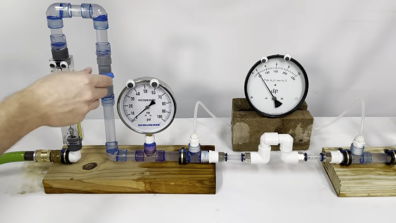
However, the real gem is the experimental test setup with clear pipes and some flow and pressure meters. We couldn’t help but notice the googly eyes on the instruments, too.
While you might need hydraulic intuition for every project, it is a good thing to know more about it. Fluid robots have certain advantages. With some work, you can even 3D print hydraulics.


I remember an article in Popular Science magazine back in the 70’s on the subject of Fluidics… using a moving fluid (ie…air, water) to control external devices. The demonstrator in the article turned on and off a light bulb.
The American Civil Engineers Handbook (1948) can be found here, https://archive.org/details/dli.ernet.4228/page/n5/mode/2up
“fluid flow in a pipe is very similar to electrical current flowing through wires” A book I had as a child compared voltage to water pressure and current to the volume of water passing in unit time. To my amusement, if you multiply these together, as you do volts and amps to get power, you get (Newtons per square metre) times (cubic metres per second) = Newton metres per second = Joules per second = watts, and the analogy is exact.
I love how in the Real World™ you explain electricity with the water analogy, but here on Hackaday, we explain water with the electricity analogy.
My favorite bit out of that is the water capacitor, which is a large cavity with a rubber membrane in the middle.
Still haven’t figured out the water analogy for transformers/inductors. Probably something with a flywheel…
Inductors are analogous to the mass of the water (or flywheel). But mutual coupling between inductors requires a stretch of the imagination. Coupled flywheels in separate piping systems is probably as close as you’ll get. Or maybe a pair of coupled pumps. But anyway the mass part being analogous to inductance is evident in waterhammer vs back EMF. In both cases we even use devices called snubbers. Heck an antenna can be a funnel… might be a bit of a stretch. But in general I think the hydraulic analogy is helpful for understanding the basics. Can’t instantaneous change current or flow of a fluid with mass, without a corresponding change in voltage or pressure.