Building your own CPU is arguably the best way to truly wrap your head around how all those ones and zeros get flung around inside of a computer, but as you can probably imagine even a relatively simple processor takes an incredible amount of time and patience to put together. Plus, more often than not you’re then left with a maze of wires and perfboards that takes up half your desk and doesn’t do a whole lot more than blink some LEDs.
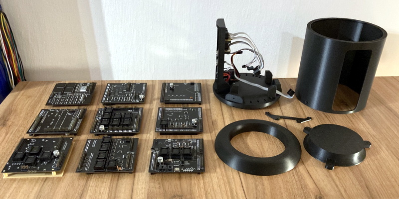
But the Pineapple ONE, built by [Filip Szkandera] isn’t your average homebrew computer. Oh sure, it still took two years for him to design, debug, and assemble, his 32-bit RISC-V CPU and all its associated hardware; but the end result is a gorgeous looking machine that runs C programs and offers a basic interactive shell over VGA. In fact with its slick 3D printed enclosure, vertically stacked construction, and modular peripheral connections, it looks more like some kind of high-tech scientific instrument than a computer; homebrew or otherwise.
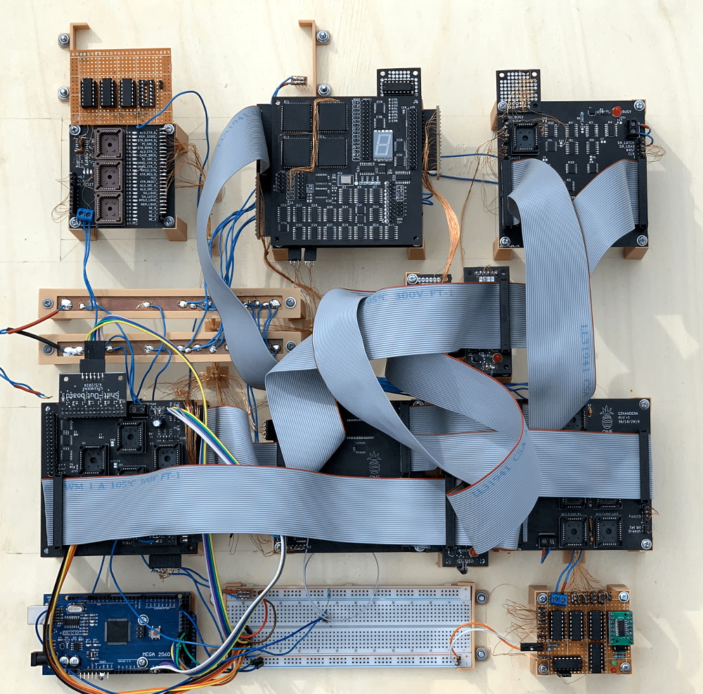
[Filip] says he was inspired to build this 500 kHz (yes, kilohertz) beauty using only discrete logic components by [Ben Eater]’s well known 8-bit breadboard computer and [Robert Baruch]’s LMARV-1 (Learn Me A RISC-V, version 1). He spent six months simulating the machine before he even started creating the schematics, let alone design the individual boards. He tried to keep all of his PCB’s under 100 x 100 mm to take advantage of discounts from the fabricator, which ultimately led to the decision to align the nine boards vertically and connect them together with pin headers.
In the video below you can see [Filip] start up the computer, call up a bit of system information, and even play a rudimentary game of snake before peeking and poking some of the machine’s 512 kB of RAM. It sounds like there’s still some work to be done and bugs to squash, but we’ve already seen enough to say this machine has more than earned entry into the pantheon of master-crafted homebrew computers.


ahh yes, the homebrew computer i totally understand the complexity of its inner workings. i did the homebrew computer building a lot in my life
It should be entirely possible to put FreeRTOS on this beast with minor effort since it supports RISC-V. Should be super reliable inside a cubesat. ;)
Might be a challenge to get all the boards in a cubesat and have room for the batteries :)
I would very like to see at least a BOM for this project. I wonder what was used, in particular, what are those square QFP chips.
Those are EEPROMs (39SF010A) – they are used for storing a program or as a lookup table.
I’ve added a BOM to “components” section in my project
That’s a beautiful machine and so cool to see it running!
But, does it run cool?
B^)
You mean: Does it run DOOM?
I feel relieved to so someones prototyping to be as cluttered and messy as mine lol.
The VGA though !!! That must have been a pain but seeing the circuit it is based on I can see why.
Some VGA standards come down to a small number of inputs for H/V Sync and active selection than others. Some are easy to do and other are difficult. He’s chosen a difficult one. Also you would get much more mileage out of some CD4040’s as counters – far less a number of chips to deal with.
Terrific project though and finished to perfection.
Fantastic work, particularly for being only 19!
As for why it’s not stable above 500kHz, without schematics it’s hard to say for certain, but here’s a few things I notice:
1. There’s a lot of PLCC-32 sockets on there. If those are flash roms used as lookup tables, and the critical path goes through more than a few of them, the latency will add up fast. Ripple carry on a 32-bit adder using 6-bit chunks would take 6*(flash speed) ns to settle in the worst case. Carry lookahead would be faster, but still likely 3*(flash speed) ns.
2. Suspicious lack of decoupling caps (though they could be on the bottom I suppose), and the boards look pretty dense for 2-layers. I imagine most chips are probably seeing pretty high impedance on VCC and GND, which probably increases the time required for everything to reach stable, well defined logic levels. This also depends a lot on the rise/fall times of the logic family being used though.
Thank you!
Yes, I use a ripple carry adder with a EEPROM chips (39SF010A) as lookup table – I have designed a carry-lookahead ALU as well, but there was a high chance for it to start oscillate (because of the way how EEPROMs are connected in a carry-lookahead ALU). 500 kHz is in range of what the ALU can deliver (at least the ALU, shifter is a whole another story).
I have nearly 200 decoupling caps on there, but I’ve found out that more of them never hurts. I used mainly a 74HCT series, but the impedance could be a problem here. With this lot of components on 2-layer PCBs, there was almost no space for me to isolate signal (or clock!) traces, even though I’ve tried my best.
I will post the schematics in the “project logs” section soon.
Risc is good.
[Robert Baruch], not [David Baruch].
Sorry! Totally my fault! It is now corrected on my end.
Doh. And ours!
Can I buy this?
This is awesome. I’m gonna have to build one for myself some day. Totally impractical. Totally cool.