[Mike Harrison] has an upcoming project which will combine a large number of flip-dot displays salvaged from buses. [Mike] thought he knew how these things worked, and had a prototype PCB made right away. But while the PCB was being manufactured, he started digging deeper into the flip-dot’s flipping mechanism.
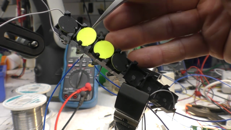
As he dismantled one of the flip-dots, he realized there was a lot going on under the hood than he realized. The dots are bistable — staying put when power is removed. This is achieved with a U-shaped electromagnet. The polarity of a driving pulse applied to the coil determines which way to flip the dot and saturates the electromagnet’s core in the process. Thus saturated, each dot is held in the desired position because the black side of the dot is made from magnetic material. But wait, there’s more — on further inspection, [Mike] discovered another permanent magnet mounted in the base. He’s not certain, but thinks its job is to speed up the flipping action.
 Besides curiosity, the reason [Mike] is studying these so closely is that he wants to build a different driver circuit to have better and faster control. He sets out to better understand the pulse waveform requirements by instrumenting a flip-dot and varying the pulse width and voltage. He determines you can get away with about 500 us pulses at 24 V, or 1 ms at 12 V, much better that the 10 ms he originally assumed. These waveforms result in about 60 to 70 ms flip times. We especially enjoyed the slow-motion video comparing the flip at different voltages at 16:55 in the video after the break.
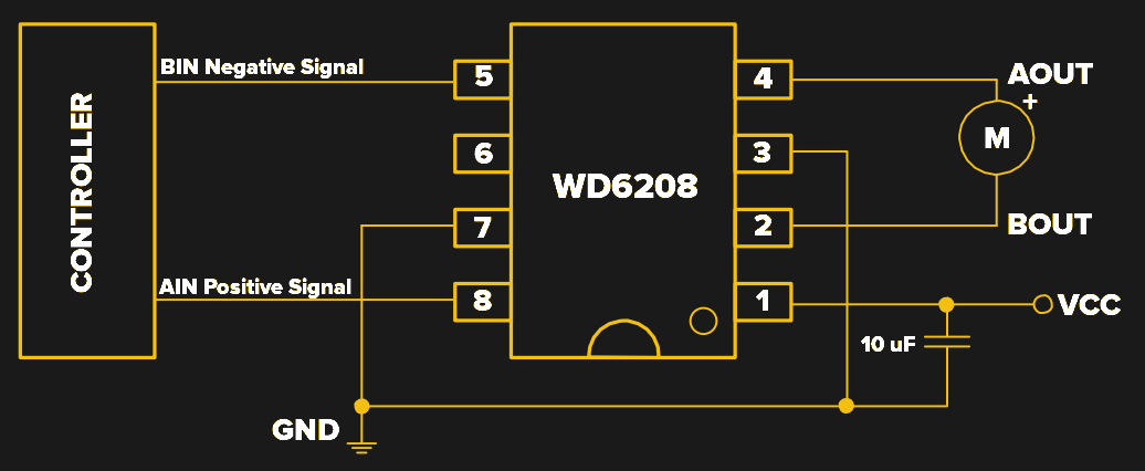
[Mike] still has to come up with the optimum driving circuit. He has tentatively has settled on a WD6208 driver chip from LCSC for $0.04/ea. Next he will determine the optimum technique to scale this up, deciding whether going for individual pixel control or a multiple sub-array blocks. There are mechanical issues, as well. He’s going to have to saw off the top and bottom margin of each panel. Reluctant to unsolder the 8500+ joints on each panel, his current idea is to solder new controller boards directly onto the back of the existing panels.
This video is a must-watch if you’re working on drivers for your flip-dot display project, and we eagerly look forward to any future updates from [Mike]. We also wrote about a project that repurposed similar panels a couple of years ago. There are a few details that [Mike] hasn’t figured out, so if you know more about how these flip-dots work, let us know in the comments below.


I always wondered if you could make each of the flip-dots like an addressable LED using a driver chip: WS2811 IC led Pixel node Module (as found on aliexpress). So perhaps the Red channel would flip the dot to yellow side and the Green channel would flip it to black. The Blue channel would drive an actual LED for flip dot backlight. You would only use 0 and 255 for values. (255,0,0) = yellow dot, (0,255,0) = black dot.
I’m now imagining a really tiny set of three flip-dots as a crude ‘RGB’ pixel cluster (maybe ‘CMY’ would be better) – would be hard to get full colour mixing but if you were far enough away then one would hope you might get more than the yellow/black of the traditional flip-dot.
No,ws2812 can’t do the 400ma you need
You don’t want to run continuous current through the coil, but you could probably use an LC network to “naturally” limit the pulse length. Or, i suppose, do it in software; if you can drive the neopixel line at 60fps then you can effectively get 16ms pulse times (still 16x what is /necessary/ but maybe close enough) even though the actual ~70ms flip time of the dot would only result in a ~15fps /actual/ flip rate. In other words you’d be over clocking the display by >4x what it is physically capable of, just the limit the current through the coils.
A bigger issue is that led drivers output constant current, whereas what you want here is constant voltage–the current starts at 0 and climbs as the pulse progresses due to the inductance of the coil.
Getting the dot to flip 180 degrees might be tough – if you reverse the field so that the dot is exactly the wrong way, it has a choice, so to speak, about which direction to turn to achieve the preferred orientation. I would hazard to guess that the permanent magnet serves to break that symmetry, giving the dot a pull away from its resting position as the electromagnet field crosses zero.
I worked at Vultron for ~8 years and we were one of two companies that made flip-dot signs; both for highway and transit bus applications. The coil is wrapped around a semi-permanent magnetic material to help “hold” the dot while de-energized. As you can imagine, a bus application has lots of vibration and one of the common requirements is to keep the sign completely black when not in use; hence the bias magnet on the base plate.
From the picture, this is a Vultron competitor sign as a Vultron sign has a flat base and hte ears are in the middle of the short sides. This allowed us to get true 180-degree flip.
I wouldn’t spend much time trying to “speed up” the flip, you want to ensure you have sufficient saturation. Speed can be developed by flipping multiple dots at the same time, but as you have likely seen, most of these are laid out in a matrix formation, I would use multiple column drivers with common row driver to speed up the update rate.
Let me know if you want more background information.
Great info, thanks!
Would you have any advice to correctly maintain dots, or maybe how to fix most common issues (like some sticking dots for example)? I wonder if some kind of degaussing kind be something to do, like with audio/video magnetic heads?
I work for Hanover Displays – we used to manufacture flip-dot signs and still service them for a few companies that continue to use them. Reply if there’s anything specific you need help with and I’ll see what I can find out.
Thanks for your reply. The only specific issue i have with one display if that some dots are quite lazy: they do not flip immediatly, but sometimes after a few seconds or a minute, or i bump the display. I wonder if i could hear these dots.
And also, since these are magnetic devices i wonder i some kind of degaussing could be a useful routine to enhance their working and/or life expectancy.
I have a few Gulton Luminator signs with the large rectangle “dots” I’ve been playing with for a while… were these your company’s design?
Hello Joe. I would love to learn more about Vultron if you have time. I’ve collected several TransDot signs over the years and have done extensive work with all types of flipdot signs from both Vultron and FP Electronics (the other company I imagine you’re referring to), and worked with flipdot bus signs from Vultron, Gulton, Luminator and TwinVision. My contact info is on my destination sign museum website Rollsign Gallery, http://www.rollsigngallery.com .If you should reach out, please let me know it’s from this post. Thanks! Joe.
Interesting to see it all graphed, along with the actual physical motion of the dot (and the very uneven bounces)
Hi Dave, one big question is how to source (enough of) them !
I have a couple of Hanover flip-dot displays, one 96×16 and the other 128×32
The 96×16 has never missed a beat, but the 128×32 has a single dot stuck on orange and a few, perhaps 4 (as you describe them), ‘lazy’ dots. They usually work, but when not, a subtle tap on the case causes them to flip. If you ever determine the cause of this behaviour, I’d love to know.
I reverse-engineered the RS485 protocol to drive these Hanover displays and so have them displaying pretty much anything I want from my PC