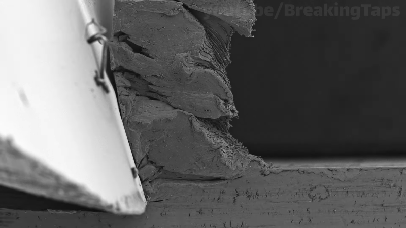
When all you’ve got is a hammer, everything looks like a nail. And when you’ve got a scanning electron microscope, everything must look like a sample that would be really, really interesting to see enlarged in all its 3D glory. And this is what [Zachary Tong] delivers with this up close and personal look at the chip formation process.
We’ve got to hand it to [Zach] with this one, because it seems like this was one of those projects that just fought back the whole time. Granted, the idea of cutting metal inside the vacuum chamber of an SEM seems like quite an undertaking right up front. To accomplish this, [Zach] needed to build a custom tool to advance a cutting edge into a piece of stock by tiny increments. His starting point was a simple off-the-shelf linear stage, which needed a lot of prep work before going into the SEM vacuum chamber. The stage’s micrometer advances a carbide insert into a small piece of aluminum 50 microns at a time, raising a tiny sliver of aluminum while it slowly plows a tiny groove into the workpiece.
Getting the multiple shots required to make a decent animation with this rig was no mean feat. [Zach]’s SEM sample chamber doesn’t have any electrical connections, so each of the 159 frames required a painstaking process of advancing the tool, pulling down a vacuum in the chamber, and taking a picture. With each frame taking at least five minutes, this was clearly a labor of love. The results are worth it, though; stitched together, the electron micrographs show the chip formation process in amazing detail. The aluminum oxide layer on the top of the workpiece is clearly visible, as are the different zones of cutting action. The grain of the metal is also clearly visible, and the “gumminess” of the chip is readily apparent too.
For as much work as this was, it seems like [Zach] had things a bit easier than [Ben Krasnow] did when he tried something similar with a much less capable SEM.


I wonder if you can make a mechanical clock like system that moves it automatically in small increments or continuously (without too much vibration). That way you don’t have to open the chamber to take snapshots. You can get higher frame rates and perhaps see some dynamic movement shortly after each increment instead of just final states of the material after it has stabilized.
Cool project. Unfortunately I cannot replicate this at home.
At the end of video he commented that he indeed tried to make such clock system, but had problems with calibrating some forces and sticktion.
I accidentally skipped over that part :). He mentioned it would take a lot of CAD work. I wonder if there is an existing solution that doesn’t require any CAD work.
I think that “Clockwork mechanisms for micrometer resolution linear stages” is not a big niche.
I was thinking more like simply using a clock or egg timer and connecting the gears to the knob. Perhaps it won’t have enough torque or won’t survive the vacuum.
@C simple clock won’t have enogh torque, egg timer won’t have enough rotations, if you add gears it won’t have enough torque. I’m not saying it can’t be done, it just can’t be done simply with what he had on hand, he would just have to spend more time fiddling with clock mechanism.
It would take less CAD work than it took him to do the measures, but he didn’t knew that beforehand :\. I think a small stepper and some off-the-shelf reductor would be enough. You can put a motor in a SEM if you put shielding around it.
I wonder if commercial batteries are vacuum proof.
@C – they are not. Vacuum proof batteries just have their own pressure chamber, most electrolytes will just evaporate under vacuum.
I like this DIY video with explanation of this process., but exactly this is also a serious application for researching cutter geometry and there are quite a lot of video’s on youtube of “chip formation”.
Also often the side of the material is polished and etched to make make the crystal structure more visible.
For example, the youtube channel youtube.com/@junjunguo/videos has a bunch of such video’s.
And normally such video’s are quite fluently, so they have many more frames which makes it much clearer in how the material deforms just in front of the cutter. (Also: the deformation generates heat, and when the deformed area is cut of, that heat is carried away with the chips). And there are many more things you can see in such video’s. I had not realized these video’s were made with an electron microscope. I just assumed an optical microscope was used.
Having to open the vacuum chamber and suck it empty again for each picture is a real nuisance. A quick search for the Phenom XL (see bill @10:11) finds: “The Phenom XL G2 Desktop SEM features full-screen images and an average time-to image of 60 seconds”, so that is still half an hour for a second of video. This really does need more automation…
Is it possible to use batteries inside a vacuum chamber? That could be combined with a uC and a stepper motor. Also, making a chamber with electrical pass through connections does look quite feasible for a bit of a handy DIY person with a small mill. With “professional” versions the connections are probably pressed in glass. But for DIY methods there are probably plenty other options. Maybe bolts and teflon washers work, or copper wires (with a knot in them for extra grip?), and then cast them in some hard epoxy.
One example is here: https://www.youtube.com/watch?v=uwh3ouvzSLk
(I am not sure that this is the original poster of the video, unfortunately)
It is instructive to see how a build-up on the edge can cause a degradation in surface finish. This workpieces that come out all rough and abrasive all of a sudden, that is probably what is happening.
This was one of the interesting things about Zach’s video: seeing how much plastic deformation under the cutting edge affected the surface finish of the remaining surface. There were big dips and ripples left behind from uneven chip formation.
Epoxy will probably outgas so much it won’t be possible to pull a sufficient vacuum. I was thinking about this and wondering if you could use pins machined with a taper, a matching taper in the teflon for the passthrough so that they seal harder under vacuum, and then vacuum grease to help the inevitable machining flaws.
But I think glass to metal seals is the right way to do this.
Believe it or not JB Weld is a favorite because it outgasses so little.
Use Torr Seal. Good to 10^-9 torr. For lubrication use Apiezon N, rated to 10^-10 torr.
For a poor mans wire feedthrough, drill a hole in the material, fill with alumina ceramic that has holes, solid core wire without insulation, and torr seal. Work torr seal into all cracks and cure. Top off with more torr seal. Used these routinely in HV work and they worked very well.
Something something spark plugs