ESP8266 Coaster Keeps Your Drink Warm

Looking for the perfect winter desk accessory? [Wq] has created a beautiful coaster made out of PCBs  that can keep your drink warm with an internal heater. (Chinese).

An ESP8266 sits as the main controller, with an additional MQTT control option, where the whole unit is powered over a USB-C connection. On board PCB traces, in the shape of a Hilbert curve, create the heating element used to heat beverages placed on the coaster, where [Wq] reports a measured resistance of the PCB trace network at 1.2 ohms. [Wq] writes that an AON6324 MOSFET replaces the D4184 that was previously being used, but might need some testing to get working properly. There are two capacitive touch sensors which has a TTP223E capacitive touch controller attached to detect input, with a multi-colored FM-3528 RGB LED for user feedback.

We love the artistry that went into building the coaster. For adventurous hackers wanting to build their own, the bill of materials (BOM), source code and board files are all available. We’ve seen everything from coasters and to PCB reflow boards, so it’s nice to see experimentation with a combination of these ideas.

Fritzing diagram of connections between the Wemos D1 board, the TP4056 board, the pushbutton and the LiIon battery

Battery-Powered ESP8266 Sensor? Never Been Simpler

Say, you’re starting your electronics journey with a few projects in mind. You have an ESP8266 board like the Wemos D1, a Li-Ion battery, you want to build a small battery-powered sensor that wakes up every few minutes to do something, and you don’t want to delve into hardware too much for now. Well then, does [Mads Chr. Olesen] have a tutorial for you! Here, you’ll learn the quick and easy way to get your sensor up and running, learn a few tricks for doing sleep Arduino environment, and even calculate how long your specific battery could last. Continue reading “Battery-Powered ESP8266 Sensor? Never Been Simpler”

ESP8266 Web Server Saves 60% Power With A 1 Ms Delay

Arduino has a library for quickly and easily setting up a simple web server on an ESP8622-based board, and [Tomaž] found that power consumption on an ESP-01 can be reduced a considerable amount by simply inserting a 1 ms delay in the right place. The reason this works isn’t because of some strange bug or oddball feature — it’s really just a side effect of how the hardware operates under the hood.

[Tomaž] uses the “hello world” example from ESP8266WebServer to explain. In it, the main loop essentially consists of calling server.handleClient() forever. That process checks for incoming HTTP connections, handles them, sends responses, exits — and then does it all over again. A simple web server like this one spends most of its time waiting.

A far more efficient way to handle things would be to launch server.handleClient() only when an incoming network connection calls for it, and put the hardware to sleep whenever that is not happening. However, that level of control just isn’t possible in the context of the Arduino’s ESP8266WebServer library.

So what’s to be done? The next best thing turns out to be a simple delay(1) statement right after each server.handleClient() call in the main loop.

Why does this work? Adding delay(1) actually causes the CPU to spend the vast majority of its time in that one millisecond loop. And counting microseconds turns out to be a far less demanding task, power-wise, than checking for incoming network requests about a hundred thousand times per second. In [Tomaž]’s tests, that one millisecond delay reduced idle power consumption at 3.3 V from roughly 230 mW to around 70 mW — about 60% — while only delaying the web server’s response times by 6-8 milliseconds.

For simple web server applications, this is is for sure a good trick to keep in mind. There are also much more advanced techniques for saving power on ESP8266-based boards; from boards that barely sip a single microamp while sleeping, to coin-cell powered boards that go so far as to modify the TCP/IP stack to help squeeze every bit of power savings possible.

ESP8266 Smart Vents Keep Tabs On Home Temps

Have you ever found that, despite having a central heating and air conditioning system, that not all the rooms in your home end up being the temperature you want them to be? Maybe the dining room gets too hot when the heater is running, or the bedroom never seems to cool off enough in the summer months. If that sounds like your house, then these motorized “smart vents” from [Tony Brobston] might be exactly what you need.

The idea here is pretty simple: an ESP8266 and a servo is built into the 3D printed vent register, which allows it to control the position of its louvers. When connected to your home automation system via MQTT, the vents allow you to control the airflow to each room individually based on whatever parameters you wish. Most likely, you’ll want to pair these vents with an array of thermometers distributed throughout the house.

While [Tony] says the design still needs some testing, he’s released smart vents in a range of sizes from 2×10 to 6×12 inches. He’s also provided excellent documentation on how to print, assemble, and program the devices. It’s clear that a lot of care and thought went into every element of this project, and we’re excited to see how it can be developed further by the new ideas and contributors that will inevitably pop up now that it’s gone public.

Want to add some automation to your HVAC, but don’t have a fancy central unit? Don’t worry, as long as your heater or air conditioner has an infrared remote, you should be able to wedge a WiFi-enabled microcontroller in into the equation.

Continue reading “ESP8266 Smart Vents Keep Tabs On Home Temps”

Section from the ESP8266 datasheet, showing maximum input voltage as 3.6V, but not mentioning ESD diodes to VCC and only talking about a snap-back circuit set to 6V.

Is ESP8266 5 V Tolerant? This Curve Tracer Says Yes!

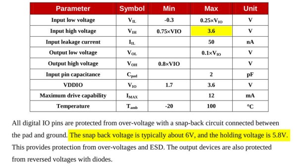
Some people state that ESP8266 is tolerant of 5 V logic levels on its GPIOs, while others vehemently disagree, pointing at the datasheet-stated 3.6 V maximum. Datasheets aren’t source code for compiling the chip, however, and aren’t universally correct and complete either. [Avian] decided to dig deeper into the claims, conduct an experiment with an actual ESP8266 chip, then share the results for all of us.

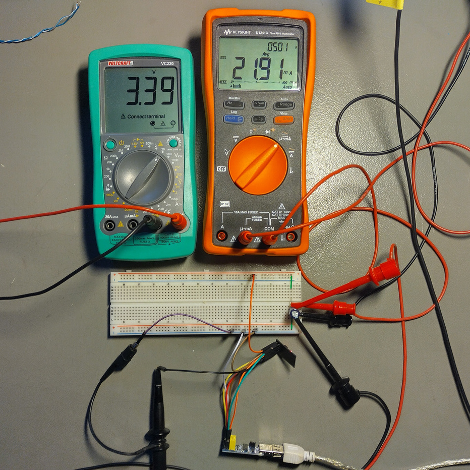
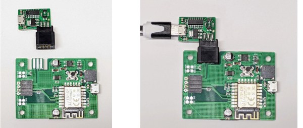
For the experiment, he used a curve tracer – a device capable of producing a wide range of voltages and measuring the current being consumed, then plotting the voltage-to-current relationship. This helps characterize all sorts of variables, from diode breakdown voltages to transistor characteristics. The curve tracer he uses is a capable and professional-looking DIY build of his, and arguably, deserves a separate write-up!

The reasoning behind [Avian]’s experiment is simple – if the pin, set to an input, starts consuming a higher amount of current at a certain voltage threshold, then there’s gotta be some chip-internal structure, intended or unintended, that would be damaged at this voltage. Curve tracer in hand, he set up an ESP-01 module to set a GPIO to input, and started increasing the voltage.

A curve tracer output graph, showing that there's no noticeable increase of current consumed across the range of 0V to 6.6V - current increasing from 0.2mA to 0.4mA in that range

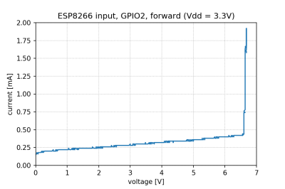
The tests have shown that, while there’s a reverse biased ESD diode from GPIO pins to ground, there don’t seem to be diodes from the GPIO pin to the VCC rail – and those are the primary concern for 5 V tolerance. There does seem to be something functionally akin to a 6 V Zener diode internally, which should clamp the voltage before it gets too way high for the chip to handle. None of that should be a problem for 5 V compatibility, and it seems fair to interpret this as a confirmation of 5 V tolerance until someone shows otherwise.

[Avian] didn’t want to destroy an ESP8266, so the experiment was conducted with a 1 K series resistor between the curve tracer and the input – which might have biased the results a bit. On the other hand, adding series resistors in front of your inputs is an overall underappreciated practice, 5 V or otherwise. He also points out that, while the pins don’t seem to be adversely impacted by the higher input voltage, the bootloader might set some of them to 3.3 V outputs on boot-up, shorting your 5 V source to your 3.3 V rail — worth keeping in mind!

[Avian]’s research journeys are fun to follow, and we recommend you check his blog out; last time, we covered his research of an innocent-looking 3.5 mm jack hiding a devious audio compensation circuit. Since we first covered the ESP8266 in 2014, we’ve been researching all the things it’s really capable of, and we brought up the topic of GPIO 5 V compatibility way back in 2016 – it’s reassuring to finally put this question to rest!

We thank [Adrian] for sharing this with us!

ESP8266 Based WiFi Game Boy Cartridge Browses WikiPedia

[Sebastian Staacks] came across his old Game Boy and was wondering (as you do) what happened to recent attempts at getting a WiFi interface wedged into a standard cartridge. After a while the conclusion was that people had been scuppered by approaching the problem in a way that made it too hard. Obviously that meant it was necessary to follow through and build something, which is precisely what he did with his WiFi Game Boy Cartridge.

A trend lately has been to hook up a fast microcontroller to a bus, then move the whole interfacing shenanigans into software. This works fine in some circumstances, but for the GB interface, it’s not so easy. The GB is powered by the Sharp LR35902, running at a smidge over 4 MHz, but its machine cycle takes four clocks giving an instruction rate of only 1 MHz. The cartridge interface presents the raw CPU bus directly. This is both good and bad. It’s good, because it enables all kinds of expansion modules, like cameras, printers, and other custom peripherals, but it’s bad because the burden of interfacing with the CPU, at its full speed, lies squarely in the cartridge’s remit.

Rather than trying to hook this bus directly to a fast microcontroller, [Staacks] has taken a different approach; by decoding the address bus with discrete logic, it was easy to derive chip selects for an embedded ESP8266 as well as a socketed EEPROM. The clock for the former was also gated and sent into the ESP8266, generating an interrupt to wake it up. The EEPROM stores a simple application whose job is to present an OSD keyboard and send requests to Wikipedia, via the ESP8266 WiFi stack. The resulting text is then displayed on the 160×144 dot matrix display. The interrupt latency of the ESP8266 was mitigated by the application simply discarding the first data byte sent to it, and retrying the access. This way the ESP8266 could spend the majority of its time dealing with wireless duties, only pausing to swap a byte now-and-then with the application. A simple solution which appears to actually work! If you’re up for building one of these and writing your own applications, you can wander over to GitHub, clone yourself a copy and crack on!

We’ve seen a few attempts at doing this before, [davedarko] tried with this project, and if you search hackaday.io you’ll get loads of GB hacks to browse. Finally a recent twitter thread also points to another effort to do something similar with Wi-Fi, but development is still ongoing. We’ll check back later!

Continue reading “ESP8266 Based WiFi Game Boy Cartridge Browses WikiPedia”

Liberating The ESP8266 From Its Development Board

While the ESP32 is clearly a superior piece of hardware, we think you’ll agree that the ESP8266 is just too useful not to have a dozen or so kicking around the parts bin at any given time. Cheap, easy to use, and just enough capabilities to bring your projects into the wonderful world of IoT. But if you really want to get the most out of it, you’ll eventually have to skip the development board and start working with the bare module itself.

It can be a scary transition, but luckily, [Ray] has collected some notes that should prove helpful for anyone looking use modules like the ESP-12F in their own custom PCBs. From different tips on making sure the power-hungry modules get enough juice, to cost cutting measures that help reduce the ancillary parts needed in your circuit design, it’s a worthwhile read for new and experienced ESP8266 wranglers alike.

An auto-reset circuit with the CH340C

For example, [Ray] talks a bit about using the infamous GPIO10 pin. This pin is on the rear of the ESP8266 module, and on many development boards, it isn’t even connected. That’s because its internally hooked up to the ESP8266’s SPI flash chip, and using it can cause problems if you’re not careful. But as explained in the blog post, as long as you make sure the flash mode is set to “dual IO” (DIO), then GPIO10 can be used just like any other free pin.

We also really liked the tip [Ray] shares at the end for making your boards more easily programmable. Sure you can leave an unpopulated header on the board, or fiddle with some pogo pin setup, but his edge connector approach is quite clever. Just slip the programmer on for the initial burn, and then after that you can update over the air.

There’s no denying how easy it is to throw something together with an ESP8266 development board, but we’ve covered so many incredible projects that have made use of the bare module’s diminutive dimensions that you’ll ultimately be missing out if you don’t cut out the middle-man.