An Adjustable High-Voltage Power Supply Built With Safety In Mind

It’s not entirely clear why [Advanced Tinkering] needs a 50,000-volt power supply, but given the amount of work he put into this one, we’re going to guess it will be something interesting.

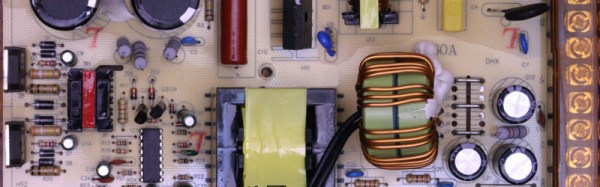
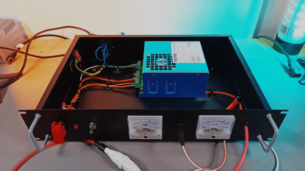
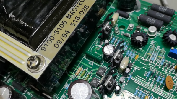
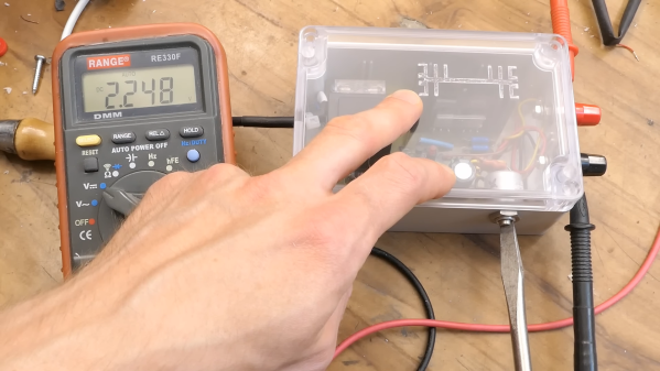
The stated specs for this power supply are pretty simple: a power supply that can be adjusted between 20kV and 50kV. The unstated spec is just as important: don’t kill yourself or anyone else in the process. To that end, [Advanced] put much effort into making things as safe as possible. The basic architecture of the supply is pretty straightforward, with a ZVS driver and an AC flyback transformer. Powered by a 24-volt DC supply and an adjustable DC-DC converter, that setup alone yields something around 20kV — not too shabby, but still far short of the spec. The final push to the final voltage is thanks to a three-stage Cockcroft-Walton multiplier made with satisfyingly chunky capacitors and diodes. To ensure everything stays safe in the high-voltage stage, he took the precaution of potting everything in epoxy. Good thing, too; tests before potting showed arcing in the CW multiplier despite large isolation slots in the PCB.

Aside from the potting, some really interesting details went into this build, especially on the high-voltage side. The 3D-printed and epoxy-filled HV connector is pretty cool, as is the special wire needed to keep arcs at bay. The whole build is nicely detailed, too, with care taken to bond each panel of the rack-mount case to a common ground point.

It’s a nice build, and we can’t wait to see what [Advanced Tinkering] does with it. In the meantime, if you want to get up to speed on handling high voltage safely, check out our HV primer.

Continue reading “An Adjustable High-Voltage Power Supply Built With Safety In Mind”

Making A Fixed Voltage Power Supply Adjustable

Switch-mode power supplies are ubiquitous. Standard off-the-shelf modules in a consistent range of form factors available from multiple manufacturers. Globalized manufacturing and trade has turned them from expensive devices into commodity parts, and they long ago replaced iron-cored transformers as the go-to choice when a high-current low-voltage mains supply is required.

[Lindsay Wilson] faced a power supply problem for a motor he was working with, it required 7.4V and no off-the-shelf power supplies were to be found with that voltage. His solution was to take a 12V supply and modify it to deliver a variable voltage so he could dial in his requirement. A Chinese-made 12v 33A switch-mode supply was purchased, and he set to work.

In the event he was able to design a replacement feedback divider incorporating a rotary potentiometer, and achieve a voltage range of 5 to 15V. A small LED voltmeter mounted next to it in the PSU case gave him a very neat result.

Modifying a switch-mode supply to deliver a different voltage is a well-worn path we’ve covered at least once before. What makes Lindsay’s article worth a read is his reverse-engineering and examination in detail of the PSU circuit. If you’d like to learn more about all the different facets of design that go into a switch-mode PSU, it’s a detailed yet readable primer. We’d suggest reading our recent series on mains and high voltage safety before cracking open a switch-mode PSU yourself, but even if you’re never going to do it there’s something to be gained from knowing in detail how they work.

We’ve featured [Lindsay]’s work here at Hackaday a few times over the years. Check out his ultrasonic transducer power supply, which might be of use were you were building the ultrasonic soldering iron we featured not long ago, his laser stripping of ribbon cables, and his tale of decapping a USB isolator chip.

Adjustable Breadboard Power Supply

psboard

This looks like a great addition to your breadboard. [Nerdz] wanted a power supply that was easily portable and adjustable. He built a custom board that plugs directly into the breadboard’s power rails. It has a pot attached to the ground of a 7805 voltage regulator so the output can be adjusted from 5V to just under the supply voltage. Anything that makes a breadboard less of a rats nest is definitely a good thing.

High-Voltage Fun With An Inexpensive Power Supply

It used to be that nearly every home had at least one decent high-voltage power supply. Of course, it was dedicated to accelerating electrons and slamming them into phosphors so we could bathe ourselves in X-rays (not really) while watching Howdy Doody. These days the trusty tube has been replaced with LEDs and liquid crystals, which is a shame because there’s so much fun to be had with tens of thousands of volts at your disposal.

That’s the impetus behind this inexpensive high-voltage power supply by [Sebastian] over at Baltic Labs. The heavy lifting for this build is done by a commercially available power supply for a 50-watt CO2 laser tube, manufactured — or at least branded — by VEVOR, a company that seems intent on becoming the “Harbor Freight of everything.” It’s a bold choice given the brand’s somewhat questionable reputation for quality, but the build quality on the supply seems decent, at least from the outside. [Sebastian] mounted the supply inside a rack-mount case, as one does, and provided some basic controls, including the obligatory scary-looking toggle switch with safety cover. A pair of ammeters show current and voltage, the latter with the help of a high-voltage resistor rated at 1 gigaohm (!). The high-voltage feedthrough on the front panel is a little dodgy — a simple rubber grommet — but along with the insulation on the high-voltage output lead, it seems to be enough.

The power supply’s 30 kV output is plenty for [Sebastian]’s current needs, which from the video below appear to mainly include spark gap experiments. He does mention that 50 kV commercial supplies are available too, but it would be tough to do that for the $150 or so he spent on this one. There are other ways to go, of course — [Niklas] over at Advanced Tinkering recently shared his design for a more scratch-built high-voltage supply that’s pretty cool too. Whatever you do, though, be careful; we’ve been bitten by a 50 kV flyback supply before and it’s no joke.

Continue reading “High-Voltage Fun With An Inexpensive Power Supply”

Lessons Learned From A High-Voltage Power Supply

When you set out to build a 60,000-volt power supply and find out that it “only” delivers a measly 50,000 volts, you naturally have to dive in and see where things can be improved. And boy, did [Advanced Tinkering] find some things to improve.

First things first: if you haven’t seen [Advanced]’s first pass at a high-voltage supply, you should go check that out. We really liked the design of that one, and were particularly impressed with the attention to detail, all of which seemed to be wisely geared to the safe operation of the supply. But as it turns out, the margin of safety in the original design wasn’t as good as it could be. Of most concern was the need to physically touch the supply to control it, an obvious problem should something go wrong anywhere along the HV path, which includes a ZVS-driven flyback and an epoxy-potted Crockcroft-Walton voltage multiplier.

To make things a little more hands-off, [AT] added a pneumatically actuated switch to the supply, along with some indicator lights to help prevent him from leaving the supply powered up. He also reworked the low-voltage DC supply section, replacing a fixed-voltage supply and a DC-DC converter with a variable DC supply. This had the side benefit of providing a little bit more voltage to the ZVS driver, which goosed up the HV output a bit. The biggest change, though, was to the potted part of the HV section, which showed signs of arcing to the chassis. It turns out that even at 100% infill, 3D printed PLA isn’t a great choice for HV projects; more epoxy was the answer to that problem. Along with rewinding the primary on the flyback transformer, the power supply not only hit the 60-kV spec, but even went a little past that — and all without any of that pesky arcing.

We thought [Advanced Tinkering]’s first pass on this build was pretty slick, but we’re glad to see that it’s even better now. And we’re still keen to see how this supply will be put to use; honestly, the brief teaser at the end of the video wasn’t much help in guessing what it could be.

Continue reading “Lessons Learned From A High-Voltage Power Supply”

Tearing Down And Improving A Professional Power Supply

[OZ2CPU] has an HP power supply that is about 30 years old. It looks brand new, though, and has three outputs and includes tracking for the adjustable positive and negative supply. After a quick demo of the unit’s features, he tears it all down so we can see inside. You can catch the video below.

Some similar supplies offer a 10-turn adjustment knob, but this one doesn’t. Inside is a beefy transformer and quite a few through-hole components. There was room to change the main adjusted pot to a 10-turn unit, so he made the mod.

Continue reading “Tearing Down And Improving A Professional Power Supply”

Linear Power Supply’s Current Limiter Is A Lesson In Simplicity

Here at Hackaday we really like to feature projects that push the limits of what’s possible, or ones that feature some new and exciting technology that nobody has ever seen before. So what’s so exciting about this single-voltage linear power supply? Honestly, nothing — until you start looking at its thermally compensated current limiting circuit.

This one is by [DiodeGoneWild], who you’ve really got to hand it to in terms of both the empirical effort he went through to optimize the circuit, as well as the quality of his explanation. The basic circuit is dead simple: a transformer, a full-wave rectifier, an LD1085 adjustable regulator — a low-dropout version of the venerable LM317 — and associated filter caps and trimmer pot to adjust the output between 2.2 and 5.5 volts.

The current limiting circuit, though, is where things get interesting. Rather than use an op-amp, [DiodeGoneWild] chose a simple discrete transistor current-sense circuit. To make it less susceptible to thermal drift, he experimented with multiple configurations of resistors and Schottky diodes over a wide range of temperatures, from deep-freeze cold to hair-dryer-in-a-box hot. His data table and the resulting graph of current versus temperature are works of art, and they allowed him to make sensible component selections for a fixed 250-mA current limit with a reasonably flat thermal response.

As for construction, it’s all classic [DiodeGoneWild], including a PCB with traces ground out with a Dremel and a recycled heat sink. He also dropped a couple of interesting build techniques, like adding leads to turn SMD tantalum caps into through-hole components. The video below shows all the build details along with the exhaustive breadboard testing.

From taking on a potentially risky magnetron teardown to harvesting lasers from headlights, there’s always something to learn from a [DiodeGoneWild] video.

Continue reading “Linear Power Supply’s Current Limiter Is A Lesson In Simplicity”