1950s Switching Power Supply Does It Mechanically

When you hear about a switching power supply, you think of a system that uses an inductor and a switch to redistribute energy from the input to the output. But the original switching power supply was the vibrator supply, which was common in automotive applications back in the middle part of the last century. [Mr. Carlson] has a 1950s-era example of one of these, and he invites us to watch him repair it in the video below.

Most of the vibrator supplies we’ve seen have been built into car radios, but this one is in a box by itself. The theory is simple. A DC voltage enters the vibrator, which is essentially a relay that has a normally-closed contact in series with its coil. When current flows, the relay operates, breaking the contact. With no magnetic field, the springy contact returns to its original position, allowing the whole cycle to repeat.

Continue reading “1950s Switching Power Supply Does It Mechanically”

Fail Of The Week: A Potentially Lethal Tattoo Removal Laser Power Supply

Caveat emptor is good advice in general, but in the wilds of eBay, being careful with what you buy could be life-saving. To wit, we present [Les Wright]’s teardown and very ginger power-up of an eBay tattoo-removal laser power supply.

Given that [Les] spent all of around $100 on this widowmaker, we’re pretty sure he knew what he was getting himself into. But he likely wasn’t quite prepared for the scale of the sketchiness this thing would exhibit. The deficiencies are almost too many to number, starting with the enclosure, which is not only made completely of plastic but assembled from individual sheets of flat plastic stock that show signs of being glued together by hand. Even the cooling water tank inside the case is pieced together this way, which probably led to the leaks that corroded the PCBs. Another assembly gem is the pair of screws the big energy storage capacitor is jammed under, presumably to hold it in place — because nothing says quality like a BOM that can’t spring for a couple of cable ties. Click through the break to read more and see the video.

Continue reading “Fail Of The Week: A Potentially Lethal Tattoo Removal Laser Power Supply”

High-Voltage Fun With An Inexpensive Power Supply

It used to be that nearly every home had at least one decent high-voltage power supply. Of course, it was dedicated to accelerating electrons and slamming them into phosphors so we could bathe ourselves in X-rays (not really) while watching Howdy Doody. These days the trusty tube has been replaced with LEDs and liquid crystals, which is a shame because there’s so much fun to be had with tens of thousands of volts at your disposal.

That’s the impetus behind this inexpensive high-voltage power supply by [Sebastian] over at Baltic Labs. The heavy lifting for this build is done by a commercially available power supply for a 50-watt CO2 laser tube, manufactured — or at least branded — by VEVOR, a company that seems intent on becoming the “Harbor Freight of everything.” It’s a bold choice given the brand’s somewhat questionable reputation for quality, but the build quality on the supply seems decent, at least from the outside. [Sebastian] mounted the supply inside a rack-mount case, as one does, and provided some basic controls, including the obligatory scary-looking toggle switch with safety cover. A pair of ammeters show current and voltage, the latter with the help of a high-voltage resistor rated at 1 gigaohm (!). The high-voltage feedthrough on the front panel is a little dodgy — a simple rubber grommet — but along with the insulation on the high-voltage output lead, it seems to be enough.

The power supply’s 30 kV output is plenty for [Sebastian]’s current needs, which from the video below appear to mainly include spark gap experiments. He does mention that 50 kV commercial supplies are available too, but it would be tough to do that for the $150 or so he spent on this one. There are other ways to go, of course — [Niklas] over at Advanced Tinkering recently shared his design for a more scratch-built high-voltage supply that’s pretty cool too. Whatever you do, though, be careful; we’ve been bitten by a 50 kV flyback supply before and it’s no joke.

Continue reading “High-Voltage Fun With An Inexpensive Power Supply”

Power Supply Efficiency Measurements

Even if you don’t have a Rohde Schwarz oscilloscope, you can still enjoy their recent video about using an oscilloscope to measure power supply efficiency. Of course, you don’t have to have a scope to do this. You can use a voltmeter and an ammeter, but it is very straightforward if you have a four-channel scope with a pair of current probes.

Of course, if you can measure the voltage and the current at the input, you can calculate the input power. Then again, most scopes these days can do the math for you. Then, you make the same measurement and calculation at the output. If you know the input and output power, you can calculate a percentage or many scopes can do it for you now.

Continue reading “Power Supply Efficiency Measurements”

Fixing A PDP-11/03 Power Supply Is Easy When You Understand It

After we last saw [David Lovett] of [Usagi Electric], he was knee-deep in trying to fix a DEC PDP-11/03 power supply, which fortunately led to a fixed PSU and a very happy PDP-11/23 system installed in the enclosure, as he covers in today’s video. Previously, we had covered his debugging attempt of this very much dead power supply, which had led [David] down many fruitless rabbitholes. By the time he was taking various components off the board to try and induce certain results, he threw in the towel and went back to the drawing board, assisted with many community comments.

The 5V rail on a DEC PDP-11/03 power supply. (Credit: David Lovett)

Much of the confusion came down to not really understanding how this PDP-11/03 PSU design works, which isn’t that crazy in hindsight, considering how quaint it is. Although [David] originally focused on the +5V rail, a small detail that was in the schematics is that the 5V rail is based around a 7805 that has its ground referenced to the -15V rail.

It is this 7805 that provides a linearly regulated 5V rail up till its current limit, at which point the control transistor gets biased sufficiently to start conducting, which eventually triggers the driver transistor that is responsible for driving the pass switch transistor. This then charges L2 from the unregulated supply, which is used effectively as a switching mode power supply until the current across the 7805 drops sufficiently that it becomes the primary 5V rail source again. This repeats at a kHz rate, making it more or less an SMPS as we know it today, but heavily reliant on the -15V rail as can be observed in the schematic. Continue reading “Fixing A PDP-11/03 Power Supply Is Easy When You Understand It”

Lessons Learned From A High-Voltage Power Supply

When you set out to build a 60,000-volt power supply and find out that it “only” delivers a measly 50,000 volts, you naturally have to dive in and see where things can be improved. And boy, did [Advanced Tinkering] find some things to improve.

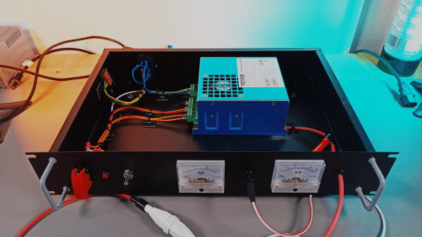
First things first: if you haven’t seen [Advanced]’s first pass at a high-voltage supply, you should go check that out. We really liked the design of that one, and were particularly impressed with the attention to detail, all of which seemed to be wisely geared to the safe operation of the supply. But as it turns out, the margin of safety in the original design wasn’t as good as it could be. Of most concern was the need to physically touch the supply to control it, an obvious problem should something go wrong anywhere along the HV path, which includes a ZVS-driven flyback and an epoxy-potted Crockcroft-Walton voltage multiplier.

To make things a little more hands-off, [AT] added a pneumatically actuated switch to the supply, along with some indicator lights to help prevent him from leaving the supply powered up. He also reworked the low-voltage DC supply section, replacing a fixed-voltage supply and a DC-DC converter with a variable DC supply. This had the side benefit of providing a little bit more voltage to the ZVS driver, which goosed up the HV output a bit. The biggest change, though, was to the potted part of the HV section, which showed signs of arcing to the chassis. It turns out that even at 100% infill, 3D printed PLA isn’t a great choice for HV projects; more epoxy was the answer to that problem. Along with rewinding the primary on the flyback transformer, the power supply not only hit the 60-kV spec, but even went a little past that — and all without any of that pesky arcing.

We thought [Advanced Tinkering]’s first pass on this build was pretty slick, but we’re glad to see that it’s even better now. And we’re still keen to see how this supply will be put to use; honestly, the brief teaser at the end of the video wasn’t much help in guessing what it could be.

Continue reading “Lessons Learned From A High-Voltage Power Supply”

PDP-11 Trouble With A Ruthless Power Supply Issue

After [David Lovett] of [Usagi Electric] was donated a few cars full of DEC PDP-11 minicomputers of various flavors and vintages, he passed on most of them to loving homes, but kept a few of them himself. One goal of this being to put together a PDP-11 system that could be more easily taken to vintage computer shows than the ‘rollable’ PDP-11s he had access to prior. Of 1980s PDP-11s, the first-generation Large Scale Integration (LSI) PDP11/03 system (so-called Q-Bus models) is among the smallest, taking up about as much space as a 1980s desktop PC, while supporting the second generation LSI PDP-11/23 cards. It all seemed so easy until [David] tried testing the PDP-11/03’s PSU and everything went south.

Despite having access to the circuit diagrams of the PSU, figuring out what was going wrong was an absolute nightmare for [David], after some easy fixes involving replacing a blown fuse and bulging capacitors failed to deliver salvation. Reading through the comments to the video, it would seem that people are generally confused about whether this PSU is a linear, switching or some other configuration. What is clear is that with the absolutely massive transformer, it looks more like a linear power supply, but with a lot of protections against over current and other failure modes built-in, all of which rely on transistors and other components that could have gone bad.

Although in round 1 the PDP-11/03 PSU won the battle, we hope that once round 2 commences [David] will have had the proverbial training montage behind him (set to ‘Eye of the Usagi’, probably) and will manage to get this PSU working once more.

Continue reading “PDP-11 Trouble With A Ruthless Power Supply Issue”