Engraving A Puzzle Box? Here’s A Collection Of Single-Line Cryptex Fonts

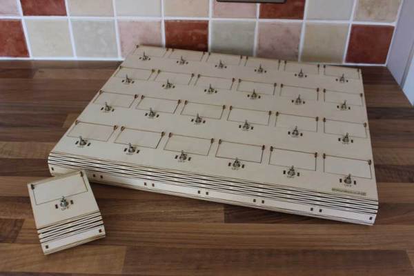
Here’s a neat resource from [MSRaynsford] that is worth bookmarking for anyone who gets creative with laser engravers, CNC routers, or drawing robots: SVGFonts are single-line symbol fonts that [MSRaynsford] created for his laser-cut and engraved cryptex puzzle boxes. They provide an easy way to engrave text as symbols.

Single-line fonts for engraving that include a runic-looking alphabet, a Greek-inspired set, and two symbol sets based on Flag Semaphore.

CNC engraving of letters and symbols is one of those things that seems simple, but is actually more complex than it may appear. It is often desirable to use a tool to engrave symbols with a single line, in much the same way a person would write them if using a pen. But fonts and art for letters and numbers aren’t normally a single line. Thankfully there is a solution in the form of Hershey text, an extension for which is included in Inkscape. It turns out that Hershey Fonts have their origin back in the 1960s, when the changing landscape of electronics and industry opened new opportunities and demanded new solutions.

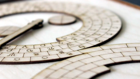
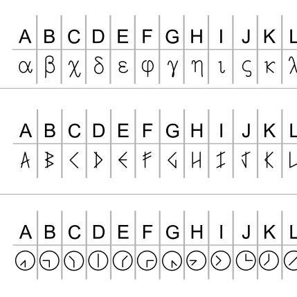
That’s why, when [MSRaynsford] needed fonts in different styles and symbols for creating his puzzle boxes, he had to design them himself and they had to be single-line vector art, just like Hershey Text. The small collection includes English letters designed to resemble a runic alphabet, a Greek-inspired series, and two coded alphabets based on flag semaphore.

Grab ’em on GitHub, because you never know when you’ll need to make a quick cryptex.

An OpenSCAD Library For All Your CNC Cutting Needs

While there’s always the edge case, there’s a strong likelihood that if you’re using OpenSCAD, you’re probably working on a CAD model that you intend to 3D print at some point. Of course that’s not to say this is all you can do in OpenSCAD, but it’s arguably what it does best. If you wanted to make artistic models, or maybe render what your new kitchen will look like, there are other tools better suited to such tasks.

But thanks to lasercut.scad, a library that [Brendan Sleight] has been working on for the last several years, we might have to reconsider our preconceived dimensional notions. Instead of designing parts for 3D printing, his library is all about creating parts intended for subtractive manufacturing. Originally (as the name implies) it was geared towards laser cutting, but the project has since evolved to support CNC routers, vinyl cutters, and pretty much anything else that can follow a DXF file.

This “clip” joint is great for acrylic.

The library has functions for creating the standard tricks used to build things from laser-cut pieces, like finger joints, captive nuts, and assembly tabs. If it was something you once saw holding together an old wooden 3D printer kit back in the day, you can probably recreate it with lasercut.scad. It even supports a pretty wild piece of rotational joinery, courtesy of [Martin Raynsford].

Don’t have a way of concentrating a sufficient number of angry photons at your workpiece? No worries. The library has since been adapted to take into account a parametric kerf width, which lets you dial in how much of a bite your particular tool will take from the material when it does the business. There are even special functions for dealing with very thin cuts, which [Brendan] demonstrates by assembling a box from sheet vinyl.

Of course, those who’ve used OpenSCAD will know there’s not an “Export for CNC” button anywhere in the stock interface. So to actually take your design and produce a file your cutter can understand, [Brendan] has included a Bash script that will run the necessary OpenSCAD incantations to produce a 2D DXF file.

[Brendan] decided to send this one in after he saw the aluminum enclosure OpenSCAD library we covered recently. If you’ve got your own pet project that bends some piece of hardware or software to your will, don’t be shy to let us know.

Array Of Useless Machines Is Useless

What’s the collective noun for a group of useless machines? A passel of useless machines? A failure? A waste? A 404?  Whatever you want to call it, [Martin Raynsford] has produced one here with this collection of 24 useless machines arranged into a 5 by 6 array. He produced it for an event at a hackerspace to amuse visitors, and it certainly seems to do the job in the video after the break.

[Martin] built the case by modifying the design of his Useless Machine kit, stretching out the case to hold multiple mechanisms. The original plan was to use a 6 by 6 matrix, but that wouldn’t fit into the laser cutter, so it ended up with 24 mechanisms in a 5 by 6 array. All of those are driven by 2 AAA batteries, and the mechanisms are efficient enough that it survived a full day of button flipping before it began to run out of juice.

Continue reading “Array Of Useless Machines Is Useless”

The Practical Approach To Keeping Your Laser In Focus

You could be forgiven for thinking that laser cutters and engravers are purely two dimensional affairs. After all, when compared to something like your average desktop 3D printer, most don’t have much in the way of a Z axis: the head moves around at a fixed height over the workpiece. It’s not as if they need a leadscrew to push the photons down to the surface.

But it’s actually a bit more complicated than that. As [Martin Raynsford] explains in a recent post on his blog, getting peak performance out of your laser cutter requires the same sort of careful adjustment of the Z axis that you’d expect with a 3D printer. Unfortunately, the development of automated methods for adjusting this critical variable on lasers hasn’t benefited from the same kind of attention that’s been given to the problem on their three dimensional counterparts.

Ultimately, it’s a matter of focus. The laser is at its most powerful when its energy is concentrated into the smallest dot possible. That means there’s a “sweet spot” in front of the lens where cutting and engraving will be the most efficient; anything closer or farther away than that won’t be as effective. As an example, [Martin] says that distance is exactly 50.3 mm on his machine.

The problem comes when you start cutting materials of different thicknesses. Just a few extra millimeters between the laser and your target material can have a big difference on how well it cuts or engraves. So the trick is maintaining that perfect distance every time you fire up the laser. But how?

One way to automate this process is a touch probe, which works much the same as it does on a 3D printer. The probe is used to find where the top of the material is, and the ideal distance can be calculated from that point. But in his experience, [Martin] has found these systems leave something to be desired. Not only do they add unnecessary weight to the head of the laser, but the smoke residue that collects on the touch probe seems to invariably mar whatever surface you’re working on with its greasy taps.

In his experience, [Martin] says the best solution is actually the simplest. Just cut yourself a little height tool that’s precisely as long as your laser’s focal length. Before each job, stick the tool in between the laser head and the target to make sure you’re at the optimal height.

On entry level lasers, adjusting the Z height is likely to involve turning some screws by hand. But you can always add a motorized Z table to speed things up a bit. Of course, you’ll still need to make sure your X and Y alignment is correct. Luckily, [Martin] has some tips for that as well.

The How And Why Of Laser Cutter Aiming

Laser aficionado [Martin Raynsford] has built up experience with various laser cutters over the years and felt he should write up a blog post detailing his first-hand findings with an often overlooked aspect of the machines: aiming them. Cheap diode laser cutters and engravers operate in the visible part of the spectrum, but when you get into more powerful carbon dioxide lasers such as the one used in the popular K40 machines, the infrared beam is invisible to the naked eye. A secondary low-power laser helps to visualize the main laser’s alignment without actually cutting the target. There are a couple of ways to install an aiming system like this, but which way works better?

[Martin] explains that there are basically two schools of thought: a head-mounted laser, or a beam combiner. In both cases, a small red diode laser (the kind used in laser pointers) is used to indicate where the primary laser will hit. This allows the user to see exactly what the laser cutter will do when activated, critically important if you’re doing something like engraving a device and only have one chance to get it right. Running a “simulation” with the red laser removes any doubt before firing up the primary laser.

That’s the idea, anyway. In his experience, both methods have their issues. Head-mounted lasers are easier to install and maintain, but their accuracy changes with movement of the machine’s Z-axis: as the head goes up and down, the red laser dot moves horizontally and quickly comes out of alignment. Using the beam combiner method should, in theory, be more accurate, but [Martin] notes he’s had quite a bit of trouble getting both the red and IR lasers to follow the same course through the machine’s mirrors. Not only is it tricky to adjust, but it’s also much more complex to implement and may even rob the laser of power due to the additional optics involved.

In the end, [Martin] doesn’t think there is really a clear winner. Neither method gives 100% accurate results, and both are finicky, though in different scenarios. He suggests you just use whatever method your laser cutter comes with from the factory, as trying to change it probably isn’t worth the effort. But if your machine doesn’t have anything currently, the head-mounted laser is certainly the easier one to retrofit.

In the past, we’ve covered a third and slightly unconventional way of aiming the K40, as well as a general primer for anyone looking to pick up eBay’s favorite laser cutter.

Video Shows Power Isn’t Everything In Laser Engraving

When it comes to power tools, generally speaking more watts is better. But as laser maestro [Martin Raynsford] shows, watts aren’t everything. He shares a brief video showing his older 100 W laser being handily outperformed by a newer 30 W machine. Shouldn’t the higher power laser be able to do the same job in less time? One might think so, but wattage isn’t everything. The 30 W laser engraves and cuts a wooden tile in just under half the time it takes the 100 W machine to do the same job, and with a nicer end result, to boot.

Why such a difference? Part of the answer to that question lies in that the newer machine has better motion control and can handle higher speeds, but the rest is due to the tubes themselves. The older 100 W machine uses a DC-excited (big glass water-cooled tube) CO2 laser, and the newer 30 W machine uses an RF-excited laser that looks a bit like a big metal heat sink instead of oversized lab glassware. Both tubes output what is essentially the same beam, but the RF tube is overall capable of a more refined, more stable, and more finely focused point than that of the glass tube. Since engraving uses only a small fraction of even the 30 W laser’s power, the finer control that the RF laser has over the low end of the power scale results in a much higher quality engraving.

Embedded below is a short video showing both machines engraving and cutting the same tile, side by side. You may wish to consider watching this one full screen, to better see the fine details.

Continue reading “Video Shows Power Isn’t Everything In Laser Engraving”

Easy Access Point Configuration On ESP8266

One of the biggest advantages of using the ESP8266 in your projects is how easy it is to get WiFi up and running. Just plug in the WiFi library, put the SSID and encryption key in your source code, and away you go. It authenticates with your network in seconds and you can get on with building your project. But things get a little trickier if you want to take your project someplace else, or distribute your source code to others. Quickly we learn the downside of using static variables for authentication.

While there are already a few solutions to this problem out there, [Martin Raynsford] wasn’t too thrilled with them. Usually they put the ESP8266 in Access Point mode, allow the user to connect, and then ask which network they should authenticate with. But he didn’t want his projects to require an existing network, and figured he could do just as well making a field-configurable AP.

Using it is simple. Once the ESP8266 starts up it will create a new network in the form of “APConfig XXXXXX”, which should be easy enough to find from your client side device. Once connected, you can go to a simple administration page which allows you to configure a new AP name and encryption key. You even have the option to create an open AP by leaving the “Password” field blank. Once rebooted, the ESP8266 will create a new network with the defined parameters.

[Martin] has also included a “backdoor” to let anyone with physical access to the ESP8266 board create a new open AP that can be used to reconfigure the network settings. During boot up there is a brief period, indicated with specific blinks of the LED, wherein you can hit the reset button and trigger the open AP. This keeps you from getting locked out of your own project if you forget what key you gave it.

If you’re not one to go the austere route, take a look at some of the more robust solutions we’ve seen for easier end-user setup of the ESP8266.