A Number Maze For Younger Hackers

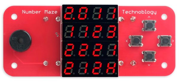
[David Johnson-Davies] has a lofty goal of building a small device to give to younger hackers on a semi-yearly basis. So this last year, he designed and created The Number Maze Game, a small handheld logic puzzle maze.

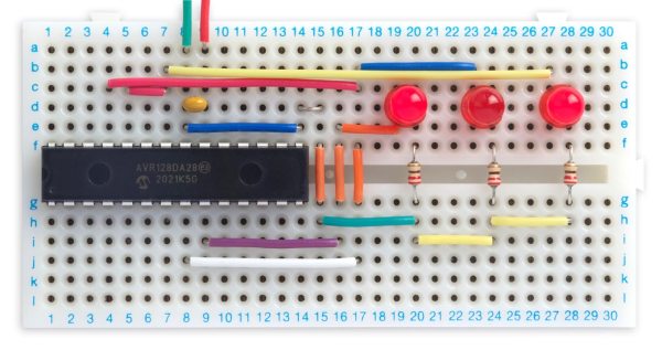
It’s based on several 4-digit seven-segment displays controlled by an AVR128DA32. Navigation is just a few push buttons and a buzzer to let you know when you’ve won. The game is simple: you jump the amount listed on the space you’re currently on, trying to get to the space labeled “H.” [David] lays out how he built it in great detail, discussing the process of designing and assembly. He also expounds on many decisions, such as using a TQFP microcontroller instead of the through-hole ATmega328P due to the I/O pin count.

The instructions and design process are so detailed we’re confident most people could easily reproduce it, especially with the code and board files. But the value of this project is not in blindly copying it. Instead, we love how something so simple can be wonderfully entertaining and valuable to younger hackers. Programming headers are included so they can add new mazes. We suspect there are many out there who would love to get something so tactile, simple, and modifiable.

Of course, we’ve seen other minimal maze games, so there’s no lack of inspiration for making some different.

Squeezing GIFs Into Even Tighter Spaces

Showing images on a TFT or OLED display with a small AVR microcontroller can be a challenge as it requires significant storage space. One solution is to compress the images, but then you need more RAM to decompress it, and that’s a whole other problem. [David Johnson-Davies] of Technoblogy couldn’t find a GIF decoder that fit his needs, so he started writing his own.

We had previously seen a minimal GIF decoder aimed at a Cortex-M0+ that required 24 K of RAM, but this technique is running on an AVR with just 12 K of RAM. Along the way, [David] uses little tricks to shave down the requirements. Since the TFT he targets is a 5-6-5 color space, those 3-byte colors become 2 bytes. The LZW lookup table is encoded as 12-bit pointers to earlier entries plus an additional pixel. However, these savings come at a cost. Animated, local color tables, transparency, interlacing, or GIF87a formatted images aren’t supported. But he ports it over to the PyBadge, which is ATSAMD51 based.

[David] provides some sample code to display a GIF from program memory and an SD card. All the code is on GitHub under a CC By 4.0 license.

Showing a new generation ATTiny on an SMD breakout plugged into a breadboard, being programmed

Come Learn About New ATtiny Generations

As the chip shortage hit, a lot of the familiar ATtiny chips have become unavailable and overpriced, and it mostly stayed the same since then. If you ever searched for “ATtiny” on your favourite electronics component retailer website, however, you’d notice that there’s quite a few ATtiny chips in stock most of the time – just that they’re from a much newer generation than we commonly see, with incompatible pinouts, slightly different architecture and longer model numbers like 412 and 3227. [David Johnson-Davies] from [technoblogy] is here to clarify things, and provide a summary of what the new ATtiny generations have to offer.

In 2019, he posted about 0- and 1-series ATtiny chips, comparing them to the ATtiny series we knew, decyphering the part numbering scheme for us, and providing a comparison table. Now, he’s returned to tell us about the 2- series ATtiny chips, merging the comparison tables together so that you can quickly evaluate available parts by their ROM/RAM size and the SMD package used. He also describes which peripherals are available on which series, as well as nuances in peripheral operation between the three generations. In the end, he reminds us of a simple way to program all these new parts – as it stands, you only need a USB-UART adapter and a 4.7K resistor.

Over the last decades, we’ve seen plenty of inspiring ATtiny projects – squeezing out everything we could out of 5 GPIOs, or slightly more for larger-package ATtiny chips. [David] has been setting an example for us, bringing projects like this function generator, this continuity tester, or an IR receiver with an OLED screen for diagnostics – all with an ATtiny85. It’s not the just pin count that’s a constraint, but the RAM and flash amounts as well – nevertheless, people have fit machine learning and an entire graphics stack into these chips before. If you’re stuck at home unable to do anything, like many of us were during lockdowns, you can always breadboard an ATtiny and see just how much you can get done with it.

Universal TFT Display Backpack Helps Small Displays Shine

TFT technology might be ancient news for monitors and TVs, but it’s alive and well when it comes to hobbyist electronics and embedded devices. They’ve now become even easier to integrate, thanks to the Universal TFT Display Backpack design by [David Johnson-Davies].

Breakout board, compatible with pinouts of most small TFT displays.

Such displays are affordable and easy to obtain, and [David] noticed that many seemed to have a lot in common when it came to pinouts and hookup info. The result is his breakout board design, a small and easy-to-assemble PCB breakout board that can accommodate the pinouts of a wide variety of TFT displays available from your favorite retailers or overseas sellers.

The board has a few quality-of-life features such as an optional connection for a backlight, and a staggered pin pattern so that different TFT boards can be pushed in to make a solid connection without soldering. That’s very handy for testing and evaluating different displays.

Interested? Head on over to the GitHub repository for the project, and while you’re at it, check out [David]’s Tiny TFT Graphics Library 2 which is a natural complement to the display backpack. [David] sure knows his stuff when it comes to cleverly optimized display work; we loved his solution for writing to OLED displays without needing a RAM buffer.

AVR Configurable Custom Logic As A Frequency Divider At 4x Chip’s Clock Speed

What a time to be alive when you can find inexpensive microcontrollers that come with programmable(ish) logic that can operate independently of the system clock. [David Johnson-Davies] recently built a proof of concept using the Configurable Custom Logic (CCL) that is available in some of the newer AVR microcontroller designs. It’s a simple implementation, a set of frequency dividers that blink three LEDs with up to a 90 MHz input signal. But the simplicity is the reason to love his write-up — you can wrap your head around it right away.

There are four lookup table (LUTs) used to form the frequency divider. Think of these like a NAND or XOR gate, but you get to decide how the output truth tables will perform. The output is fed into a sequencer which can be configured as a D/JK flip-flop or a D/RS latch, plus you can specify the signal edge, and of course define the clock source. An interesting trick here is to hold the G input of both D flip-flops high by feeding them LUTs set to all ones. Note that the output of the first divider (PA3) is feeding the external input (PD2) of the second divider.

While the CCL is configured using the C code you flash to the microcontroller, it’s a hardware peripheral capable of operating independent of the chip’s system clock. The AVR128DA28 that’s used here tops out at 24 MHz (double that if you use the PLL) but [David] got reliable results from his clock divider feeding a signal as high as 90 MHz to the input pin. Of course you have the option of feeding internal clock signals to the CCL, but that wouldn’t seem nearly as interesting here. For the demo, [David] is actually toggling an IO pin which is connected to PA2 as the external input for the logic. Make sure you click through to his write-up linked above as he does an excellent job of walking through the sample code (just a couple-dozen lines to set this all up). Here’s the datasheet for this chip (PDF, page 447 for pertinent registers) and for a deeper dive the appnote on CCL (PDF).

So what is this all good for? We already saw an answer to that question back in January when [SM6VFZ] used the CCL peripheral to build a software-defined switch-mode converter. How awesome is that?

Smoothing Big Fonts On Graphic LCDs

Here’s a neat little trick: take the jaggies out of scaled fonts on the fly! This technique is for use on graphic displays where you might want to scale your fonts up. Normally you’d just write a 2×2 block of pixels for every area where there would have been one pixel and boom, larger font. Problem is, that also multiplies each empty area and you end up with jagged edges in the transitions that really catch your eye.

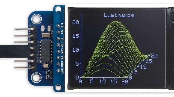
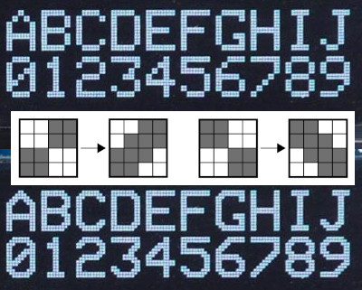
[David Johnson-Davies] entered big-brain mode and did something much cleverer than the obvious solution of using multiple font files. Turns out if you analyze the smoothing problem you’ll realize that it’s only the angled areas that are to blame, horizontal and vertical scaling are nice and smooth. [David’s] fix looks for checker patterns in what’s being drawn, adding a single pixel in the blank spots to smooth out the edge incredibly well!

The technique has been packaged up in a simple function that [David] wrote to play nicely in the Arduino ecosystem. However, the routine is straightforward and would be quick to implement no matter the language or controller. Keep this one in your back pocket!

Now if all you have on hand is an HD44780 character LCD, that one’s arguably even more fun to hack around on just because you’re so limited on going beyond the hard-coded font set. We’ve seen amazing things like using the custom character slots to play Tetris.

Simple Sprite Routines Ease Handheld Gaming DIY

Making your own handheld games is made much easier with [David Johnson-Davies’] simple sprite routines for the Adafruit PyBadge and PyGamer boards. Sprites can be thought of as small, fixed-size graphical objects that are drawn, erased, moved, and checked for collision with other screen elements.

xorSprite() plots an 8×8 sprite, moveSprite() moves a given sprite by one pixel without any flicker, and hitSprite() checks a sprite for collision with any screen elements in a given color. That is all it takes to implement a simple game, and [David] makes them easy to use, even providing a demo program in the form of the rolling ball maze shown here.

These routines work out-of-the-box with the PyBadge and PyGamer, but should be easy to adapt to any TFT display based on the ST7735 controller. The PyGamer is the board shown here, but you can see the PyBadge as it was used to create an MQTT-enabled conference badge.

If you really want to take a trip down the rabbit hole of sprite-based gaming graphics, you simply can’t miss hearing about the system [Sprite_TM] built into the FPGA Game Boy badge.