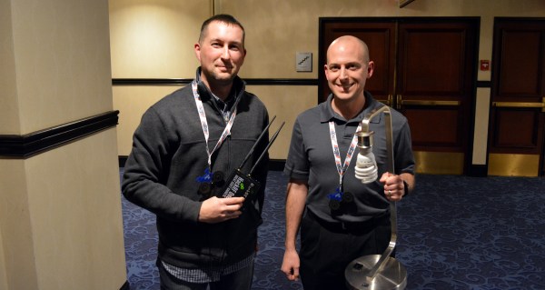
The first talk at 2016 Shmoocon was a great one. Joseph Hall and Ben Ramsey presented their work hacking Z-Wave, a network that has been gaining a huge market share in both consumer and industrial connected devices. EZ-Wave uses commodity Software Defined Radio to exploit Z-Wave networks. This is not limited to sniffing, but also used for control with the potential for mayhem.
This Thursday, December 10th at 5pm PST we will be hosting a live HackChat about aircraft. If it’s man-made and it files, it’s on topic! Full scale and model planes, helicopters, multicopters, gyros, blimps and gliders will be on the agenda. Our host this week will be Hackaday Community Editor [Adam Fabio] who is also the author of this well-written blog entry. In addition to being an electrical engineer, [Adam] brings 30 years of experience as a Radio Control model enthusiast. Over the years he’s worked as a professional R/C Blimp Pilot for the New York Islanders Hockey team and as an aerial photographer. On the full-scale aircraft side, he’s designed radar and air traffic control software used to keep the skies safe over land and sea.
Aircraft HackChat starts Thursday at 5pm PST (here’s a timezone cheat sheet if you need it). Participating in this live chat is very simple. Those who are already part of the Hacker Channel can simply click on theTeam Messaging button. If you’re not part of the channel, just go to the hacker Channel page, scroll to the bottom of the “TEAM” list in the left sidebar and click “Request to join this project”.
HackChat takes place in the Hacker Channel every few weeks and is a friendly place to talk about engineering and the projects you’re working on.
Although GRC (the GNU Radio Companion) uses the word radio, it is really a graphical tool for building DSP applications. In the last post, I showed you how you could experiment with it just by using a sound card (or even less). However, who can resist the lure of building an actual radio by dragging blocks around on a computer screen?
For this post and the accompanying video, I used an SDRPlay. This little black box has an antenna jack on one end and a USB port on the other. You can ask it to give you data about a certain area of the RF spectrum and it will send complex (IQ) data out in a form that GRC (or other DSP tools) can process.
The SDRPlay is a great deal (about $150) but if you don’t want to invest in one there are other options. Some are about the same price (like the HackRF or AirSpy) and have different features. However, you can also use cheap TV dongles, with some limitations. The repurposed dongles are not as sensitive and won’t work at lower frequencies without some external help. On the other hand, they are dirt cheap, so you can overlook a few little wrinkles. You just can’t expect the performance you’ll get out of a more expensive SDR box. Some people add amplifiers and converters to overcome these problems, but at some point it would be more cost effective to just spring for a more expensive converter.
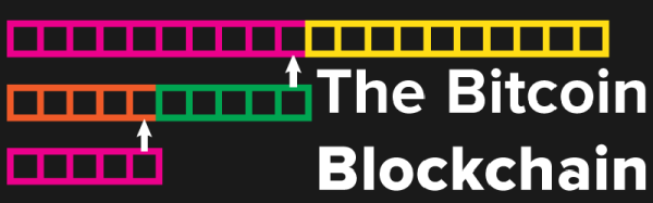
Bitcoin, the libertarian’s dream currency, is far past the heady days of late 2013. When one Bitcoin was worth $1000 USD, there was no end to what could be done; new, gigantic mining rigs were being created, every online store jumped onto the bandwagon, and the price of Bitcoin inevitably crashed. Right now, the exchange rate sits at about $280 USD per coin, valuing all the Bitcoins ever mined somewhere around $4 Billion USD. That’s a lot of coins out there, and a lot of miners constantly verifying the integrity of the greatest thing to come from the Bitcoin community: the blockchain.
The bitcoin is just a record, or the ledger, of every transaction that has ever occurred on the Bitcoin network. It’s distributed, and the act of mining coins creates new blocks, or another set of data committed to the blockchain for eternity. While magical Internet money™ is by far the most visible product of the blockchain, developers, investors, and other people in the know are gushing about the possibilities of what can be done with a distributed record that can’t practically be altered and can’t be deleted.
[Jon Matonis], a figurehead for the entire cryptocurrency movement, recently said Bitcoin has become the strongest computer in the world, and stronger than all of the top 500 supercomputers combined. All of this computational power is effectively funneled in to verifying the integrity of the blockchain.
Bitcoin and other cryptocurrencies are not just a completely anonymous payment system; that’s only a side effect of the blockchain. The blockchain is the only inherently valuable part of a bitcoin; each transaction is logged in the blockchain, providing incredible security over how every coin is spent. No currency in the history of mankind has ever had a record of how every dollar or denarius is spent, and at the very least makes for very interesting economics research. Now, thousands of researchers across the globe are wondering what else the blockchain can do; tapping the power of the most powerful computer on the planet must have some interesting applications, and in the last few months, a few ideas have popped up.
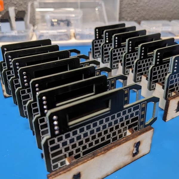
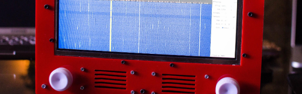
What do you get if you cross a software defined radio (SDR) and an iconic children’s drawing toy that we are sure is a trademarked name? If you are [devnulling], you wind up with the Etch-A-SDR. The box uses an Odroid C1, a Teensy, and the ubiquitous RTL-SDR.
The knobs work well as control knobs (as you can see in the video below). When you are bored listening to the radio, you can reset the box and go into Etch-a… um, drawing mode. The knobs work like you’d expect and you can even erase the screen with a vigorous shake.
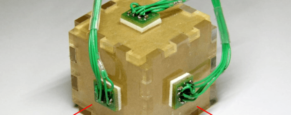
There comes a time when you need to wire up three, four, or more identical i2c devices to a common microcontroller. Maybe you’re thinking about driving 128 seven-segment displays with eight of those MAX6955 16-way digit drivers, or maybe you have a robot full of joints–each of which needs a BNO055 inertial sensor for angle estimation. (See above.) Crikey! In both of those cases, you’re best bet might be a schnazzy I²C device that can do most of the work for you. The problem? With a single I²C bus, there’s no standard way defined in the protocol for connecting two or more devices with the same address. Shoot! It would’ve been handy to wire up three BNO055 IMUs or eight MAX6955s and call it a day. Luckily, there’s a workaround.
We’ve seen some clever tricks in the past for solving this problem. [Marv G‘s] method involves toggling between a device’s default and alternate address with an external pin. This method, while clever, assumes that the device (a) has an alternate I²C address and (b) features an external pin for toggling that address.
I’ll introduce two additional methods for getting the conversation started between your micro’ and your suite of identical sensors. The first is “a neat trick,” but somewhat impractical for widespread use. The second is far more production-worthy–something you could gloat over and show off to your boss! Without further ado, let’s get started with Method 1.
Lastly, if you’d like to follow along, feel free to check out the source code on Github.
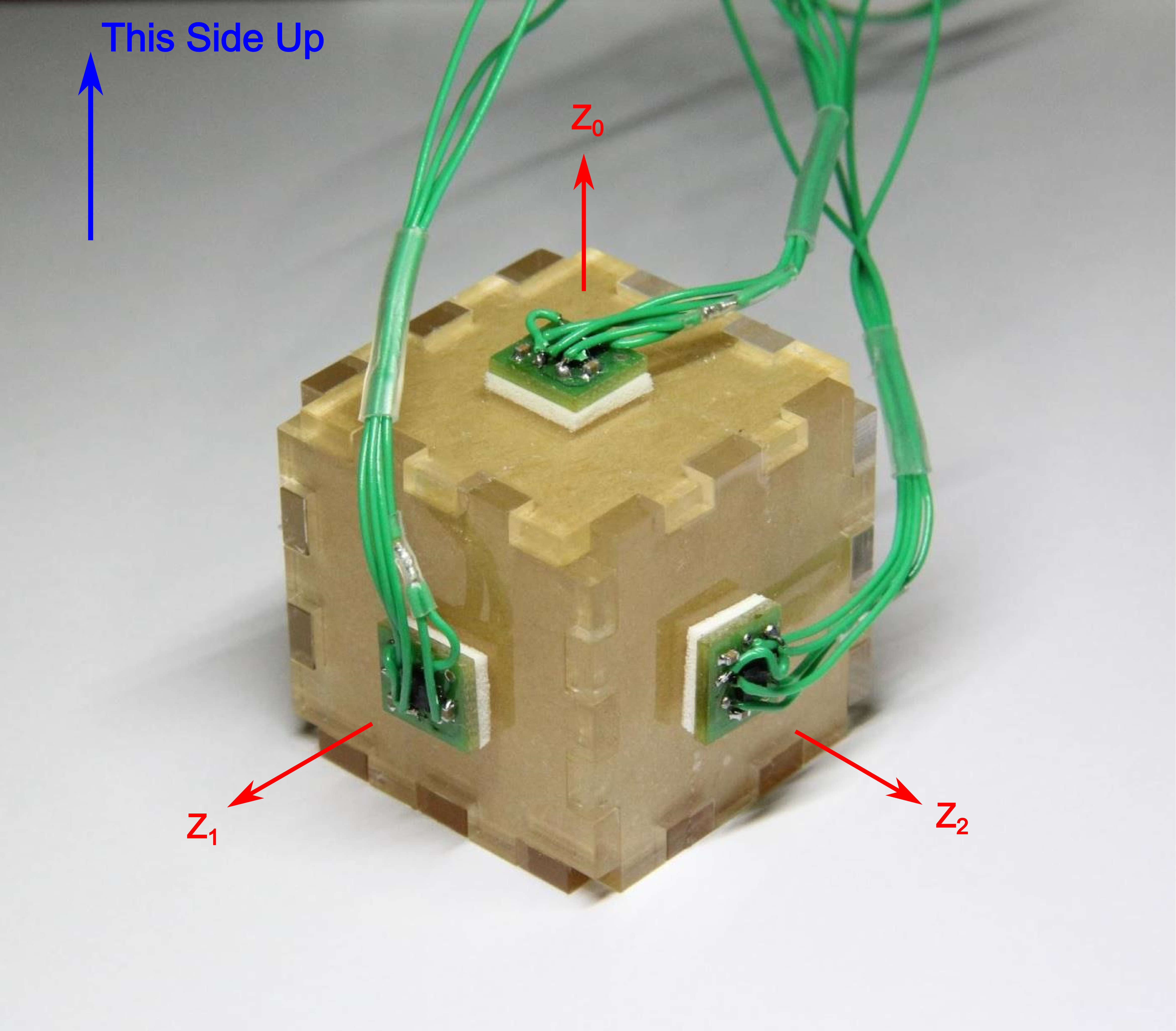
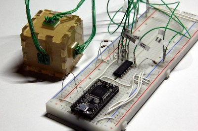
In both methods, I’m using the same sensor setup to check that each circuit behaves correctly. I happened to have a bunch of extra BMA180s on the bench, so I rolled out an example based on these chips. Back in the day, the BMA180 was a pretty common three-axis digital accelerometer. It has an I²C interface with two optional addresses. For the purpose of this example, I’m fixing them all with the same address. I’ve mounted three of these guys on mutually perpendicular axes of my acrylic “test cube,” and I’m reading each chip’s Z-axis. In this configuration I can easily pick out the gravity vector from the corresponding sensor as the data goes flying by my serial port window. If I can uniquely address each sensor and read the data, I’ve got a working circuit.
Method 1: Splicing Clocks into Chip-Selects
This method tips its hat towards SPI in that it behaves in an oddly similar fashion. If you’re feeling rusty on SPI, here’s a quick recap.
A Quick SPI Refreshment:
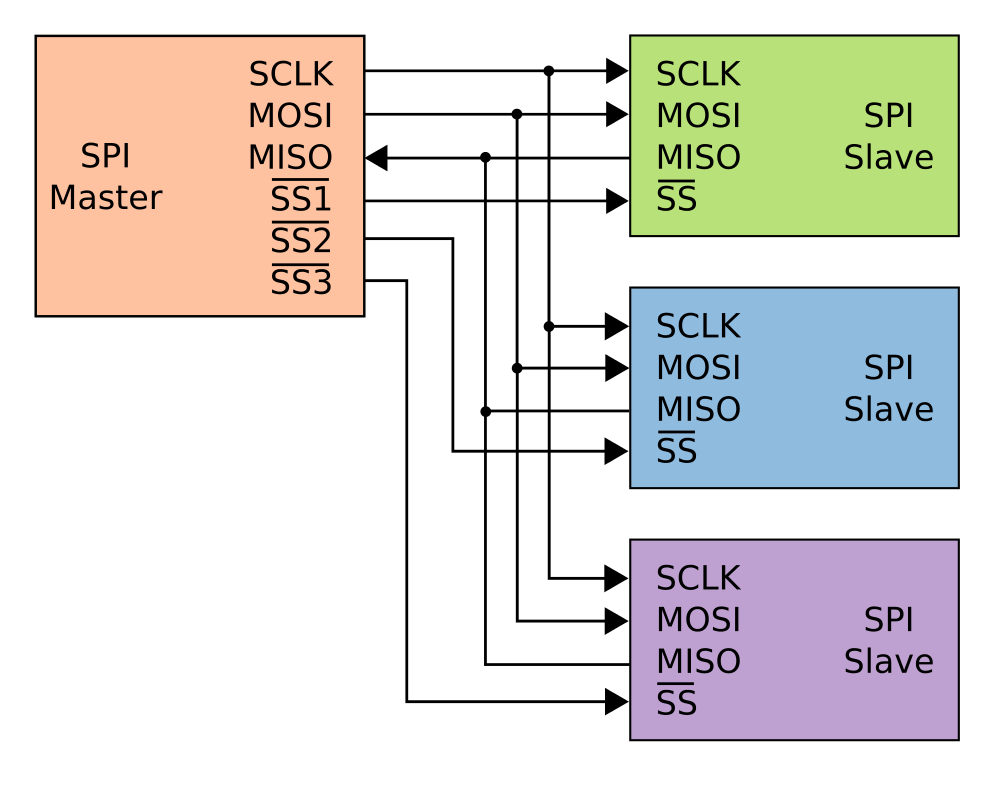
SPI, like I²C, is another protocol that shares both its clock and data lines with multiple slave devices. The difference, though, lies in the addressing scheme to talk to these devices that share the same bus. With SPI, while clock and data lines are shared, devices are addressed with separate chip-select (CS) lines.
The master microcontroller dedicates a unique output pin to each device (~SS1, ~SS2, and ~SS3 in this illustration). When the master micro’ wants to talk to a device, it asserts that device’s chip-select input pin by pulling it to logic LOW, and the conversation begins over the data bus. With the chip select LOW, the corresponding slave listens to the data on the bus. Meanwhile, all other devices ignore the conversation between the master and it’s chosen slave by keeping their bus pins in a high impedance state.
Giving I²C Its Own Chip-Selects:
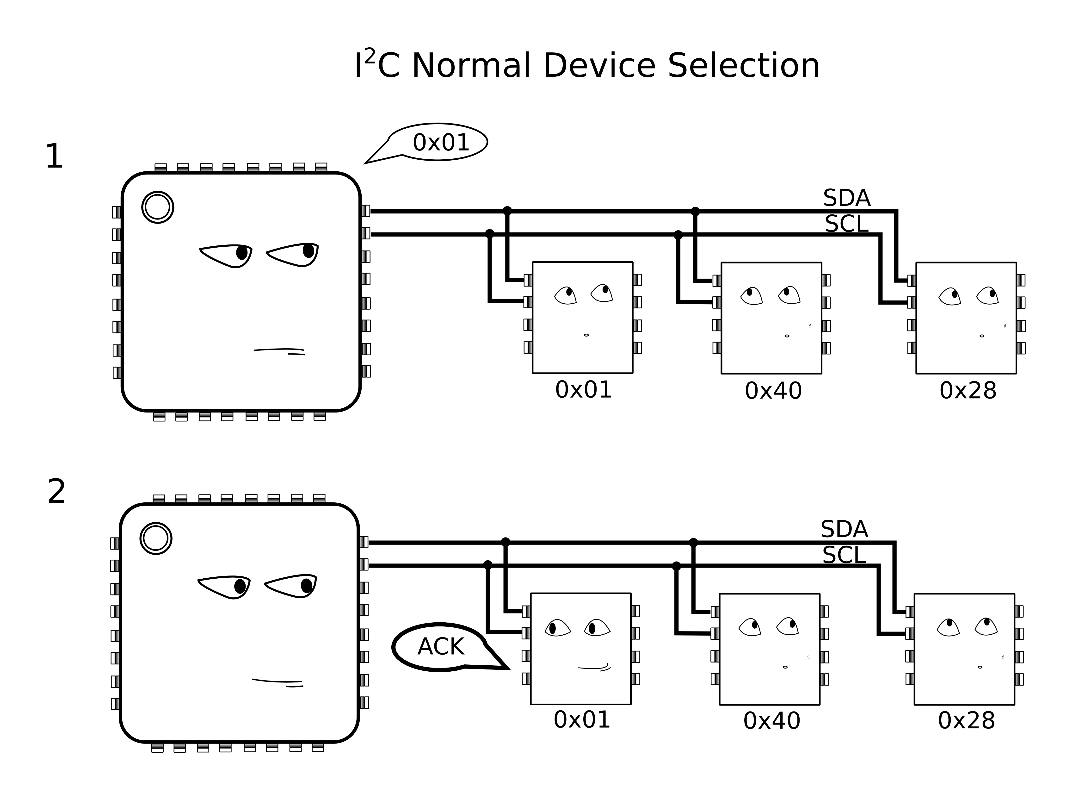
With I²C, Clock (SCL) and Data (SDA) lines are still shared between all I2C slave devices, but the addressing scheme happens by sending a message heard by all devices on the bus. To single out one device on the shared bus, the master first passes down the address of the slave device it wants to talk to, after which that slave replies with an ACKnowledge, and all other slaves ignore the data that follows until both data transmission is complete and the bus is “released.”
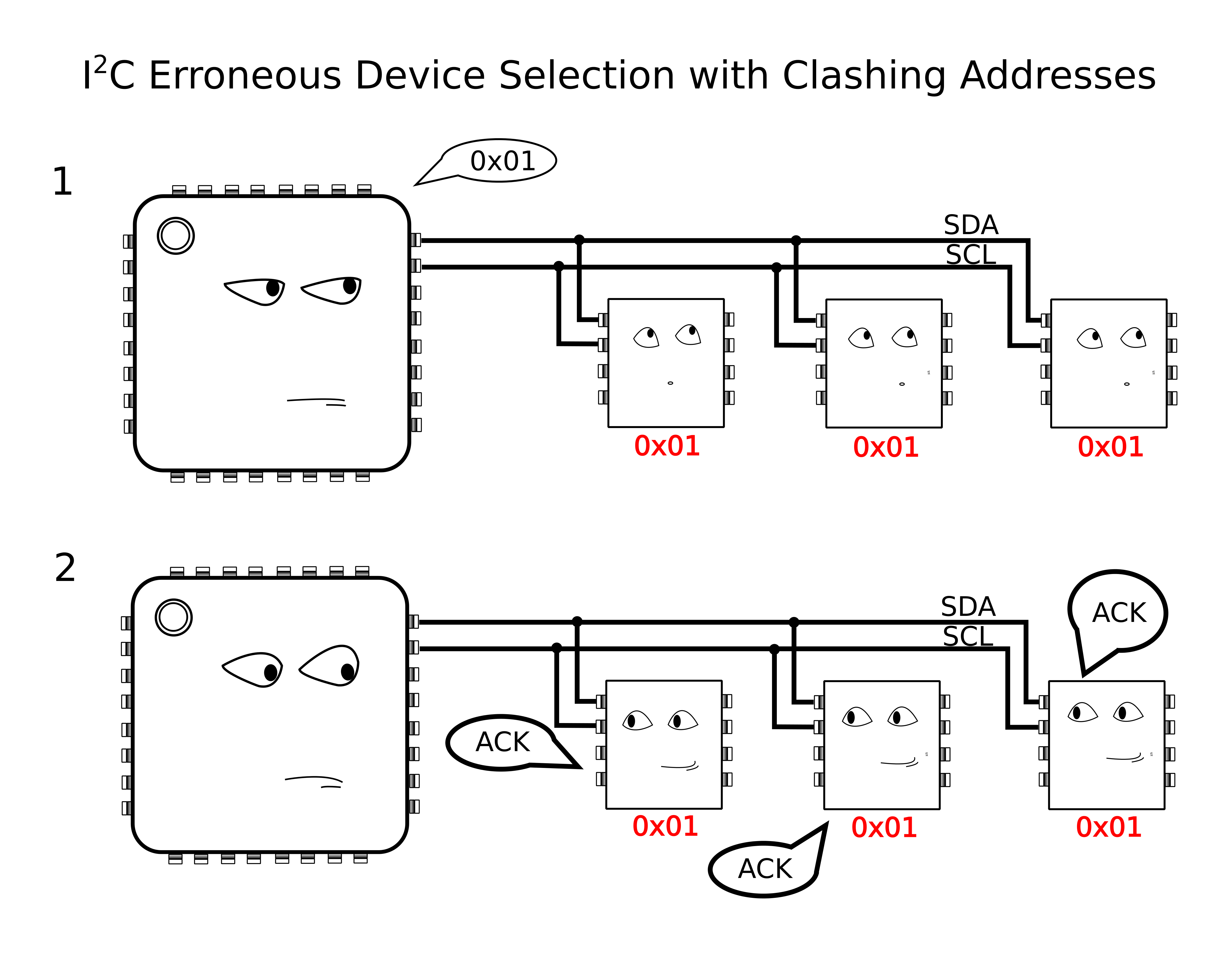
Because we have the problem of multiple devices with shared addresses, in theory, all of these devices would reply when the master passes down their shared address, and there’s no way for the master to single out a single device. In reality, this behavior is undefined on the I²C protocol.
Yikes! Anything goes when we wander away from defined behavior, so we try to avoid these things in practice.
The solution?
According to the I²C spec, It just so happens that an I²C slave device will ignore changes on the data line (SDA) provided that the clock line (SCL) is held high. In this method, I’ll “split” the SCL line into multiple SCL lines such that each shared I²C device gets its own SCL. By selectively rerouting the clock to each I²C device one-at-a-time, I’ve essentially turned the SCL line into a “chip select.”
To chop up that clock line, I’ll need a demultiplexer. A demultiplexer (or decoder) takes a logical input and reroutes it to one of several outputs based on the binary select lines.
I’ve dropped in the 74AC11138 eight-way demultiplexer for this task. It’s fast, capable of switching at megahertz rates, and its outputs default to logic HIGH. That second note is handy since idle SCL lines also default to logic HIGH.
The setup is shown in a simplified schematic above. In it, I’m using a Teensy 3.0 posing as the I²C bus master. To the right of the Teensy is the collection of identical chips, BMA180 accelerometers in this case. In the middle is the 74AC11138 eight-way demultiplexer.
Cons of this Method:
There’s a minor drawback with this technique, though, in that it doesn’t support I²C’s clock-stretching feature. Taking a step back, this method assumes that the SCL line is inherently unidirectional, controlled by only the I²C bus master. In other words, we’re making the assumption that data on the SCL line is only sent from master to slave and never the other way around. If your I²C slave devices implement clock-stretching, however, this assumption breaks down.
What is Clock Stretching?
Clock stretching is a method defined by the I²C protocol where the chip needs to “buy itself more time” and holds the SCL line low, hence, signalling to the master that it’s not ready for the upcoming data. In this scenario, the slave actively controls the SCL line, and it happens to be the only case where data moves up the SCL line from slave to master. In a setup with our demultiplexer between the master and our set of identical slaves, these slaves won’t be able to send back the clock-stretching signal to the master to indicate that they aren’t ready for data, if they happen to implement clock stretching. That said, clock stretching is a pretty rare feature among I²C-compatible devices, so this method is likely to work among a number of chips out now.
More Next Week
That’s all for Method 1. Thanks for tuning in, and check back next week for a slightly-more-professional method of tackling this same problem.
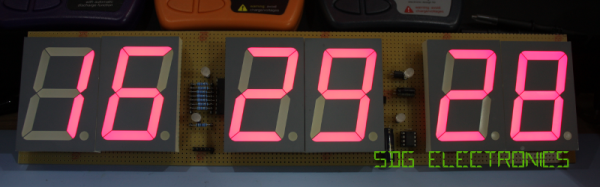
[Steve Gardner] wants an accurate clock for his bench. Of course the only option most engineers will accept for something like this a clock they’ve built themselves. In fact, this is his second time around as his first was an OLED based system using one of those sweet Maxim TCXO’s that keep time for years with negligible drift.
This build is going to be dead accurate as well since he plans to roll in a GPS source. But for now he’s covering the display build itself and will use another clock source IC at first. The display is a set of six 2.3″ 7-segment displays on protoboard. Bonus points for all the tidiness in his point to point soldering!
You may think this is a super simple project, and in a way it is. But [Steve] does an amazing job of dotting all the i’s and crossing all the t’s in a way that is beneficial to learn for all of your prototyping. For instance, he’s combining some 7-segment displays with 5mm LEDs as the colons. He mentions checking the peak wavelength of the displays to match the LEDs when choosing components. The design is also well-planned on graph paper. This may be just for use in illustrating the video but is a great practice in your own prototyping.
We’re not sure if there’s some movie magic involved here as his first burning of code to the PIC microcontroller results in a fully working device — impressive. Looking at his entire presentation, if you follow the workflow that [Steve] uses in his engineering, you’re doing it right!


 I’ve dropped in the 74AC11138 eight-way demultiplexer for this task. It’s fast, capable of switching at megahertz rates, and its outputs default to logic HIGH. That second note is handy since idle SCL lines also default to logic HIGH.