Tiny Two-Digit Thermometer Has Long Battery Life

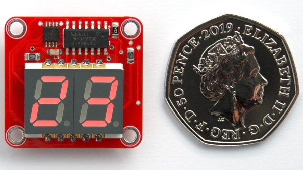
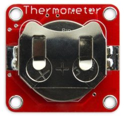
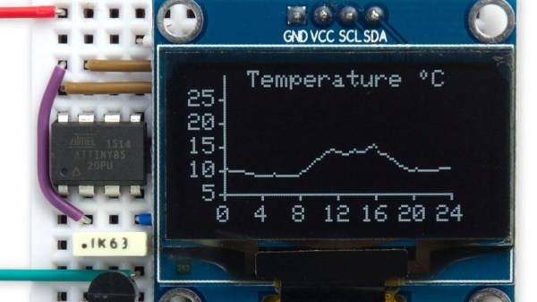
Like most of his work, this tiny two-digit thermometer shows that [David Johnson-Davies] has a knack for projects that make efficient use of hardware. No pin is left unused between the DS18B20 temperature sensor, the surface mount seven-segment LED displays, and the ATtiny84 driving it all. With the temperature flashing every 24 seconds and the unit spending the rest of the time in a deep sleep, a good CR2032 coin cell should power the device for nearly a year. The board itself measures only about an inch square.

You may think that a display that flashes only once every 24 seconds might be difficult to actually read in practice, and you’d be right. [David] found that it was indeed impractical to watch the display, waiting an unknown amount of time to read some briefly-flashed surprise numbers. To solve this problem, the decimal points flash shortly before the temperature appears. This countdown alerts the viewer to an incoming display, at the cost of a virtually negligible increase to the current consumption.

[David]’s project write-up explains how everything functions. He also steps through the different parts of the source code to explain how everything works, including the low power mode. The GitHub repository holds all the source files, and the board can also be ordered direct from OSH Park via their handy shared projects feature.

Low power consumption adds complexity to projects, but the payoffs can easily be worth the time spent implementing them. We covered a detailed look into low power WiFi microcontrollers that is still relevant, and projects like this weather station demonstrate practical low power design work.

DIY Button Matrix Lights Up And Speaks I2C

[David Johnson-Davies] always wanted an illuminated button matrix for projects, but cost was never very friendly. That all changed when he discovered a cheap source of illuminated pushbuttons on Aliexpress, leading to this DIY 4×4 illuminated button matrix design which communicates over I2C. The button states can be read independently of setting the light pattern, and an optional interrupt signal gets pulled low whenever there is a change detected. Not bad for one PCB plus about $10-worth in components!

The device uses every single pin on an ATtiny88, and because each button gets its own pin the keypresses can be detected with pin-change interrupts. The state reporting of buttons over I2C is unambiguous, even when multiple buttons are pressed simultaneously. A simple protocol provides all the needed functionality, and all connections are brought to the board’s edge to allow for easily tiling multiple panels.

The GitHub repository contains the code and PCB files and [David] helpfully shared the board files to OSH Park and PCBWay for easy ordering. In addition, he provides two demos (Tacoyaki and Tacoyaki+) which are games related to the classic Lights Out to show off the matrix.

Get Twelve Charlieplexed PWM Outputs From An ATtiny85

Most of us are aware that charlieplexing can drive a large number of LEDs from a relatively small number of I/O pins, but [David Johnson-Davies] demonstrates adding another dimension to that method to create individually controlled PWM outputs as well. His ATtiny85 has twelve LEDs, each with individually-set brightness levels, and uses only four of the five I/O pins on the device.

Each LED can be assigned a brightness between 0 (fully off) and 63 (fully on). The PWM is done by using one of the timers in the ATtiny85 to generate a periodic interrupt, and the ISR for the interrupt takes care of setting the necessary ratios of on and off times for each charlieplexed output. The result? Twelve flicker-free LEDs with individually addressable brightness levels, using an 8-pin microcontroller and just a few passive components on a tiny breadboard. There’s even one I/O pin left on the ATtiny85, for accepting commands or reading a sensor.

[David] really wrings a lot out of the ATtiny series of microcontrollers with his compact projects, like his Tiny Function Generator (which recently got an update.) He also demonstrated that while charlieplexing is usually used with LEDs, charlieplexing can be used with switches just as easily.

Program This Badge In Lisp

This hardware badge is a computer programmed with Lisp. You can write your own programs right on the badge using the built-in keyboard, as long as you know Lisp.

If there’s one thing we really like to see, it’s people advancing their own projects based on inspiration from others. The Lisp Badge by [David Johnson-Davies] is a perfect example. With an interface inspired by [Voja Antonic’s] hardware design for the 2018 Hackaday Belgrade Conference Badge, this version is an upgrade of an earlier single-board Lisp machine, now sporting an integrated keyboard.

Unlike the Belgrade badge, which is programmed in BASIC, this new badge is programmed in uLisp, a subset of common lisp designed for microcontrollers. Let’s face it, BASIC is retro, but Lisp is even more so, only pre-dated by FORTRAN as the oldest high-level language. So, if you’re into retro-style programming on small devices (physically small, that is), you should consider building one of these.

A 16 MHz ATmega 1284P serves as the badge’s brain, allowing storage for 2,816 Lisp cells, while the 256×64 pixel OLED display shows 8 lines of 42 characters in 16 gray levels. A full complement of I/O connections includes four analog inputs, two analog outputs, I2C, SPI, serial, and a handful of GPIOs for interfacing with just about anything. Power comes from a LiPO battery, which at a nominal voltage of 3.7 V doesn’t quite meet the datasheet requirements for running the processor at 16 MHz, although it seems to work fine in practice. Really cautious builders could opt for a 12 MHz crystal transplant to avoid any possibility of problems.

The keyboard layout is optimized for uLisp programming: unnecessary keys have been removed and the all-important parenthesis are afforded their own dedicated keys on the bottom row. This is presumably for convenience of use, but we suspect this will also make it easier to replace the parenthesis key switches when they inevitably wear out from overuse [obligatory Lisp/parenthesis joke].

As far as entering uLisp programs, you can simply use the keyboard. The built-in editor buffers a full screen of text, and includes parenthesis matching that highlights each pair as you type. We’re guessing that we won’t see Emacs implemented in the near future, so this bracket management is a great feature for a badge-based editor. If you find the keyboard difficult to type on, you can also enter programs over the serial port.

The other thing we really like to see is open-source projects. [David] doesn’t let us down on this point, either. The Eagle design files for the PCB as well as the source code for the badge are available on GitHub. The PCB is also shared on OSH Park, and there are detailed instructions for installing the bootloader and uploading the code.

If programmable badges is your thing, also check out the 2018 Hackaday Supercon Badge, the successor the Belgrade design.

Thanks to [Sven] for the tip!

Drawing On An OLED With An ATtiny85, No RAM Buffers Allowed

Small I2C OLED displays are common nowadays, and thanks to the work of helpful developers, there are also a variety of graphics libraries for using them. Most of them work by using a RAM buffer, which means that anything one wants to draw gets written to a buffer representing the screen, and the contents of that buffer are copied out to the display whenever it is updated. The drawback is that for some microcontrollers, there simply isn’t enough RAM for this approach to work. For example, a 128×64 monochrome OLED requires a 1024 byte buffer, but that’s bad news if a microcontroller has only 512 bytes of RAM in total like the ATtiny85. [David Johnson-Davies] has two solutions: a Tiny Graphics Library that needs no RAM buffer and an even slimmer Tiny Function Plotter, which we’ll discuss in order.

Tiny Function Plotter works on both SSD1306 and SH1106-based displays.

[David]’s Tiny Graphics Library works by taking advantage of a feature of SH1106 driver-based displays: the ability to read the display over I2C as well as write to it. With the ability to perform read-modify-write on a section at a time, using a large RAM buffer can be avoided. The only catch is that the library only works with OLEDs using the SH1106, but the good news is that these are very common at the usual Chinese resellers. ([David] notes that SH1106 is sometimes misspelled as “SSH1106”, so keep that in mind when searching.)

What about all those other SSD1306-based OLED displays out there? Are they out of luck? Not quite. [David] has one more trick up his sleeve: his Tiny Function Plotter works on the SSD1306 and also requires no RAM buffer. It’s unable to write text, but it can easily handle drawing graphs plotting things like values over time while needing very little overhead.

Another approach we’ve seen for using OLEDs driven by microcontrollers with limited memory is the solution [Michael] used in Tiny Sideways Tetris, which was done in part by realizing the smallest screen element he needed was a 4×4 block, and using that premise as the basis of a simple compression scheme.

Pic16maze secret maze game

PIC16Maze Upgrades Secret Maze Game

We really like it when a reader is inspired by something they see on Hackaday, build on it, and let us know so we can pass it on. In this case, [Vegipete] made a secret maze game using a minimal number of parts and some neat software trickery.

It’s built around an 8-pin PIC16F18313 microcontroller, uses a joystick for input, and nine WS2812 LEDs to display the player and the surrounding maze walls. His inspiration was [David Johnson-Davies’] minimalist secret maze game built around the 8-pin ATTiny85. In that one, [David] cleverly used charlieplexing to get four pins to control four LEDs and four pushbuttons. [Vegipete’s] use of the WS2812 LEDs allowed him to control the LEDs with just one pin, and also get color while using three pins for the joystick and its button. He may use another pin in the future for sound and vibration.

He goes into some detail on the WS2812 protocol, how communication is done with the LEDs using just one pin and different pulse-lengths to represent 0 and 1. We’ll leave you to see his post for more depth but basically, he introduces a module on the PIC called the Configurable Logic Cell (CLC) which makes this easy and frees up processor cycles for the user’s code to do other things.

Secret maze wall bits
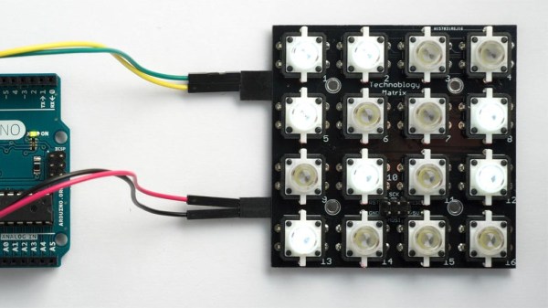
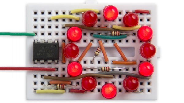
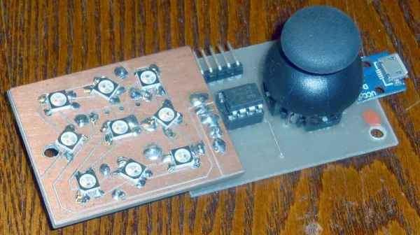
His source code is available on request but he does detail a neat software trick he uses for rotating the view. It may be confusing for some but as you move through the maze, your viewpoint rotates so that up is always the direction you’re facing. Luckily, the walls surrounding the user can be represented using 8-bits, four for east, west, north, and south, and four more for the corners. The maze is stored as a bitmap and from it, 8-bit values are extracted for the current position, each bit representing a wall around the position. To rotate the walls to match the user’s current orientation, the bits are simply shifted as needed. Then they’re shifted out to set each LED. Check it out in the video below.

It works very well despite the minimal interface and part count.

Continue reading “PIC16Maze Upgrades Secret Maze Game”

IR Detective Eases Development With Compact Decoding

Hardware development often involves working with things that can’t be directly perceived, which is one reason good development tools are so important. In appreciation of this, [David Johnson-Davies] created the IR Remote Control Detective to simplify working with IR signals. While IR remote controls are commonplace, there are a number of different protocols and encoding methods in use across different brands. The IR Detective takes care of all of that with three main components, none of which are particularly expensive. To use the decoder, one simply points an IR remote at the unit and presses one of the buttons. The IR Detective will identify the protocol, decode the signal, and display the address and command related to the key that was pressed. The unit doesn’t consist of much more than an ATtiny85 microcontroller, a small OLED display, and an IR receiver unit. The IR receiver used is intended for a 38 kHz carrier, but such receivers can and do respond to signals outside this frequency, although they do so at a reduced range.

As a result, not only is the unit useful for decoding IR or verifying that correct signals are being generated, but the small size and low cost means it could easily be used as a general purpose receiver to add IR remote control to other devices. It’s also halfway to bridging IR to something else, like this WiFi-IR bridge which not only interfaces to legacy hardware, but does it across WiFi to boot.