Color Changing Clock Gets A Pi Zero Heart

Hackaday reader [Don] dropped by the tip line recently to let us know about the latest version of his color-changing LCD clock project. This is his second version of the hardware which makes some pretty big improvements over the original, including moving from the Pi B to the Pi Zero and an internal simplification of the wiring. He mentions the next revision of the project will focus on Google Home integration, which should be interesting to see.

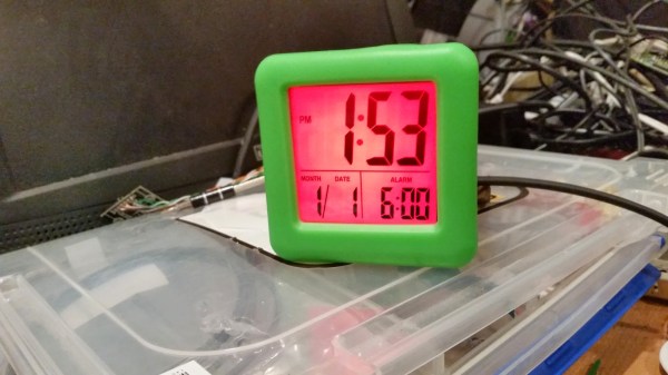
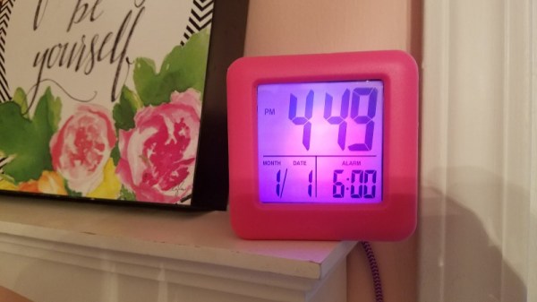
As a father of two pre-school age children, he was looking for a way to help his kids understand the concept of time and scheduled activities. Colors and shapes come fairly easy to children of this age, but time and how it relates to the day is a bit more difficult for them especially as their comprehension of numbers is still developing. [Don] reasoned that even if they couldn’t read the numbers on the clock yet, if he had the display change colors to indicate different periods of the day (sleep, play, cleanup, etc), it would not only keep them on schedule, but reinforce the meaning of the numbers on the screen.

ShiftBrite installed in the projector.

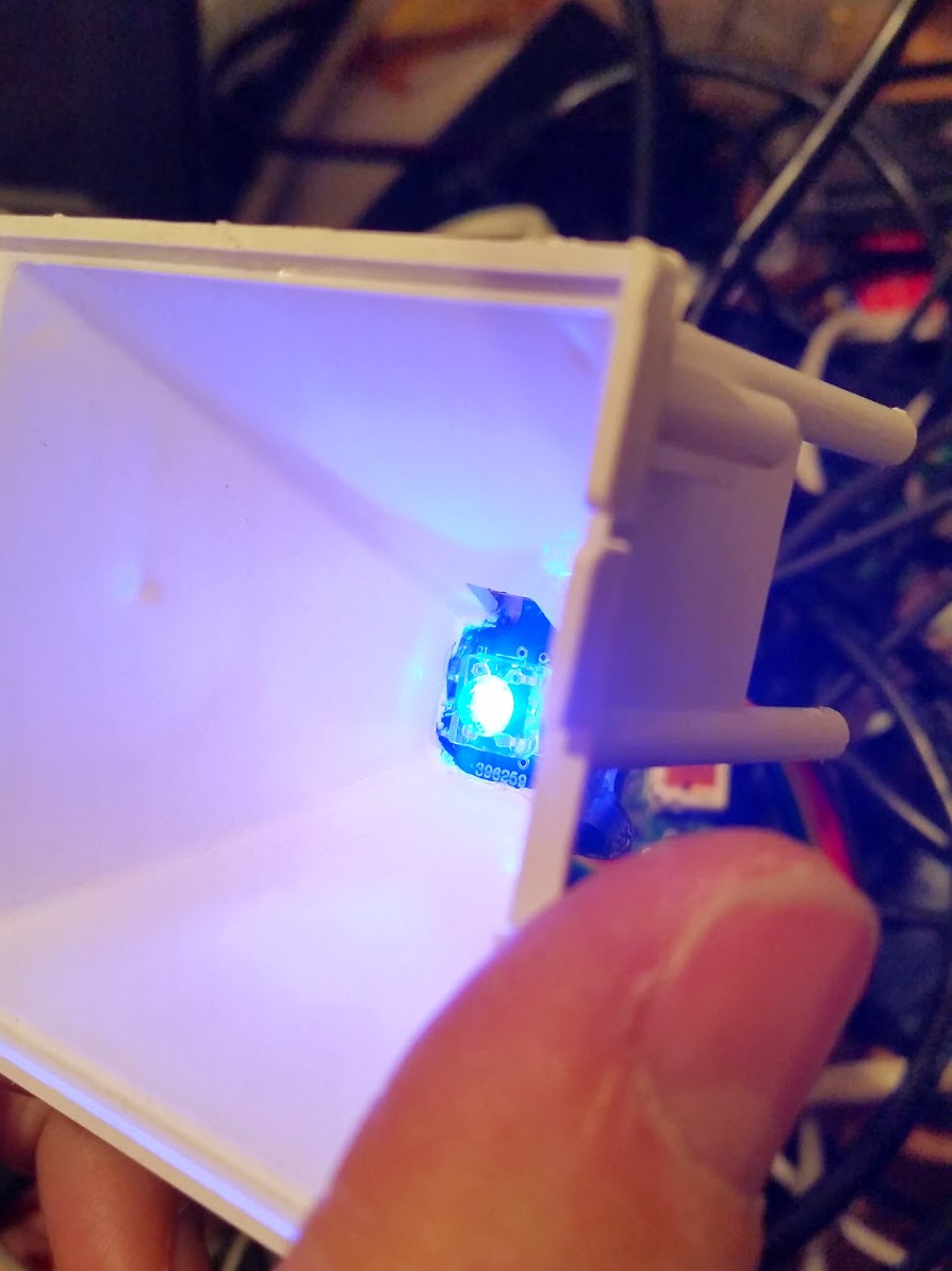
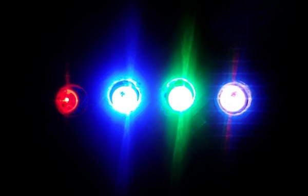
The project was made infinitely easier by a lucky find at a local retailer. For $10 he got a kid-friendly looking clock that utilized a simple projector to backlight the LCD display. This meant [Don] would just need to swap out the stock lighting module for a controllable RGB LED, and the hardware modifications would essentially be complete.

Even the Pi Zero fits perfectly inside the case of the clock, the only modification necessary was cutting a little hole in the back for the Pi’s micro USB port. His earlier version used an external Pi B connected to the clock via CAT5, so getting it all integrated into the one device is a huge improvement, especially when little kids are involved. Moving the Pi and its 5 V pins into the clock itself also allowed [Don] to drop the voltage regulator required previously.

With the basic hardware for a color changing LCD clock together, the rest of the project was just a matter of software. After some research, [Don] came across RPi-ShiftBrite by [Hive13] and made his own fork which added some features necessary for his project, namely the ability to quickly set the ShiftBrite to a specific color on the command line. To schedule the color changes, he used the very slick minicron: a web-based tool to create and monitor Linux cron jobs.

The Pi itself does not actually interface with the clock, and with no onboard RTC it’s necessary to keep it updated with NTP or else the times will become desynchronized. It can be necessary to sync the Pi’s clock to the Internet as often as every hour to make sure the colors shift at the appropriate times. The addition of a RTC module like the DS1307 could alleviate this issue and might be something to consider for a future revision.

All told, a fantastic project and something we’ll be sure to keep our eyes on as it progresses. We’ve seen our share of unique Raspberry Pi powered clocks, and even a few color changing ones, but this approach is easily the most straight-forward we’ve seen.

Continue reading “Color Changing Clock Gets A Pi Zero Heart”

Color Changing Clock Uses PCB Digits

There’s an old saying, that you should do everything at least twice. Once to learn how to do it, and then a second time to do it right. Perhaps [Zweben] would agree, since he wasn’t satisfied with his first Neopixel clock and proceeded to build another one. One lesson learned: soldering 180 tiny solder joints isn’t much fun. This time, [Zweben] set out to make a printed circuit board and redesign the clock to make it easier to assemble.

The clock uses multiple copies of a single circuit board. The board holds Neopixel strips in a 7-segment arrangement. Each board can also hold all of the electronics needed to drive the clock. Only the first board gets the microcontroller and other circuits.

Continue reading “Color Changing Clock Uses PCB Digits”

4-LED Octal Clock Demands Colorful Math

We’ve all seen LED clocks where RGB LEDs are used to display time. It seems like the simpler the interface, the more likely you’d need to do math to figure out the time. This Octal Clock by [Alex Kurrasch] proves the point by using only four LEDs: the top two show hours and minutes, and the bottom two LEDs are multipliers.

Using octal numbering, [Alex] translates the data using a Venn diagram of color mixing. The mapping uses 1 as red, 2 as green, followed by yellow, blue, magenta, and cyan. It ends with 7 as white (all on) and 0 as black (all off).

As the time changes, a fading algorithm changes the display to match. He offers the time of 7:38pm as an example in the grid shown here. Base-8 math is provided; don’t worry, you’ll get really good at this if you make your own wristwatch version… people will learn to never ask you about the time.

The clock uses a ATMega64 running assembly language firmware with a DS1306E+ RTC chip keeping track of time. The enclosure is cool too; [Alex] milled the case out of mahogany and the front and back plates are anodized aluminum. The unique looking diffusers on the LEDs are actually paraffin, a trick that [Elliot Williams] mentioned in his recent article on diffuser materials.

Who Could Resist A Color Coded Clock?

[Luc] wanted to make a clock like no other. He knows that the territory is well-trod, especially in the area of minimalist design. Undeterred, [Luc] came up with a fresh design that uses the resistor color code to display the time. He’s calling it the Nerd’s Ultimate Watch.

It doesn’t get much more minimalist than four RGB LEDs. Each one illuminates in the color that represents the digit in the current time. For instance, I’m typing this sentence at 1:37PM. The clock uses 24-hour time, so let’s call it 13:37. Using resistor color code time, that’s 1, 3, 3, 7, or brown, orange, orange, violet.
Continue reading “Who Could Resist A Color Coded Clock?”

Colorful Clock

A Colorful Clock For Toddlers

[Don] and his wife were looking for a way to teach their two-year old daughter how to tell time. She understood the difference between day and night, but she wasn’t old enough to really comprehend telling the actual time. [Don’s] solution was to simplify the problem by breaking time down into colored chunks representing different tasks or activities. For example, if the clock is yellow that might indicate that it’s time to play. If it’s purple, then it’s time to clean up your room.

[Don] started with a small, battery operated $10 clock from a local retailer. The simple clock had a digital readout with some spare room inside the case for extra components. It was also heavy enough to stay put on the counter or on a shelf. Don opened up the clock and got to work with his Dremel to free up some extra space. He then added a ShiftBrite module as a back light. The ShiftBrite is a high-brightness LED module that is controllable via Serial. This allows [Don] to set the back light to any color he wants.

[Don] already had a Raspberry Pi running his DIY baby monitor, so he opted to just hijack the same device to control the ShiftBrite. [Don] started out using a Hive13 GitHub repo to control the LED, but he found that it wasn’t suitable for this project. He ended up forking the project and altering it. His alterations allow him to set specific colors and then exit the program by typing a single command into the command line.

The color of the ShiftBrite is changed according to a schedule defined in the system’s crontab. [Don] installed Minicron, which provides a nice web interface to make it more pleasant to alter the cron job’s on the system. Now [Don] can easily adjust his daughter’s schedule via web page as needed.


Bi-color LED Matrix Clock Uses Point-to-point Construction

[Daniel] wanted his child to stay in bed until a semi-decent time each morning. The problem is the kid doesn’t know how to read a clock, so [Daniel] built him a clock. Yeah, doesn’t make much sense to us either, but we’ve used our own shaky premises for projects so who are we do judge?

He used a bi-color 8×8 LED matrix as the clock display. What caught our eye is the point-to-point soldering he used for the three strip boards that make up the device. Note the use of a drill-bit to break the traces when needed. Each board has its own purpose; the matrix drive, the logic board, and the power board. A PIC 18F4550 lets [Daniel] control the clock via USB, and takes care of lighting up the hour as a red number when it’s time to sleep, and a green one when it’s okay to arise. There’s a flashing pixel for seconds, and a binary readout of minutes along the bottom.

We’ve asked [Daniel] to post a schematic and an image of the clock face when displaying the time. No word yet but we’ll keep our eye on it. In the mean-time, check out this clock that uses an RGB 8×8 LED matrix.

Hot Resistors Used For Color-changing Clock Face

[Sprite_TM] built a full clock display using thermochromic paint. This picks up where he left off with his paint-based 7-segment display prototype. He never really saw that design through to a finished project, but he recently came across the leftover paint and decided to do something with it. Instead of making thin traces on a PCB he’s heating up resistors mounted on protoboard. Each resistor has been coated with the black/light grey paint after getting a rough sanding on the tops of the packages. Run around 500mW through a segment and they heat up enough to change the paint to light grey. Once shut off, the segments gradually fade over the next 60 seconds.