A 65-in-1 The 2024 Way

If necessity is the mother of invention, nostalgia must be its stepmother, or its aunt at the very least. The desire to recreate long-obsolete devices simply because they existed while we were growing up is a curious trait, but one that’s powerful enough to drive entire categories of hardware hacking — looking at you, retrocomputing buffs.

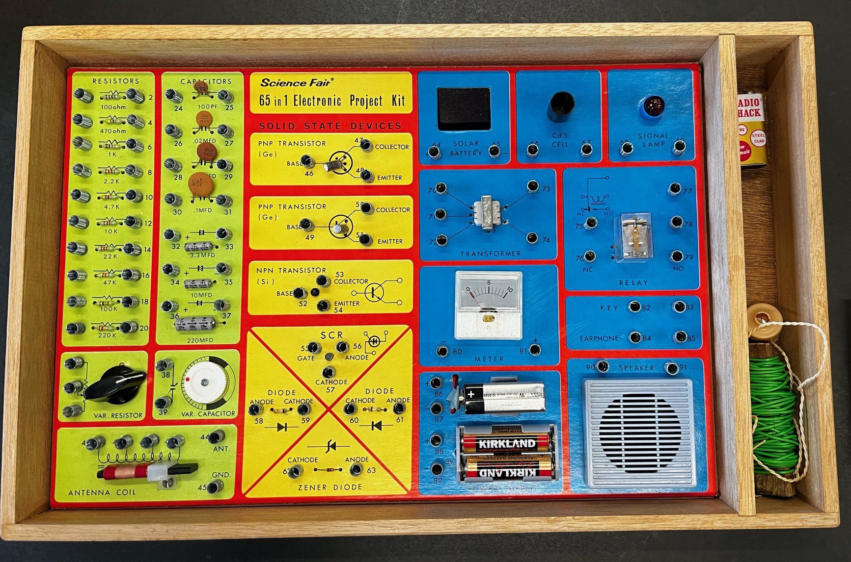
Hardware nostalgia isn’t all about 6502s and Z80s, though. Even more basic were the electronic toys of the 1970s, such as the Radio Shack 65-in-1 kit that [Tom Thoen] is currently recreating. The 65-in-1 was a breadboarding kit aimed at the budding electrical engineer, with components mounted to colorful cardboard by spring terminals. The included “lab manual” had circuits that could be quickly assembled using a handful of jumper wires. It was an endlessly fascinating toy that undoubtedly launched many careers, present company included.

The original 65-in-1 was $21.95 in 1976, or about $120 today.

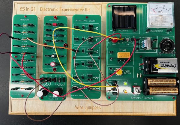
While the passage of time may not have dulled [Tom]’s memories of his original 65-in-1, technology has marched on, meaning that certain allowances had to be made to create a modern version. He wisely eschews the cardboard for PCBs, one for each of the major component blocks provided in the original, and uses female header connectors in place of the springs. Component choice is tailored for the times; gone are the ferrite rod antenna and variable capacitor of the original, as well as the incandescent lamp, which is replaced by an LED that would have been a significant fraction of the kit’s $21.95 price back in 1976. There’s no BOM yet, so we can’t say for sure if any of the transistors are germanium, but it’s clear that there aren’t any of the old TO-1 cans. But dismay not, originalists, for the meter, relay, CdS photocell, and “solar battery” all made the final cut.

[Tom] has done some beautiful work here, with more to come. We imagine that 3D printing could be used to recreate some details like the original Morse key and speaker grille. We love the laser-engraved backing board, too, as it captures some of the charm of the original’s wooden box. This isn’t the only love for the “Science Fair” brand we’ve seen lately, either; the nostalgia seems to be contagious.

A Classroom-Ready Potentiometer From Pencil And 3D Prints

If you need a potentiometer for a project, chances are pretty good that you’re not going to pick up a pencil and draw one. Then again, if you’re teaching someone how a variable resistor works, that old #2 might be just the thing.

When [HackMakeMod] realized that the graphite in pencil lead is essentially the same thing as the carbon composition material inside most common pots, the idea for a DIY teaching potentiometer was born. The trick was to build something to securely hold the strip while making contact with the ends, as well as providing a way to wipe a third contact across its length. The magic of 3D printing provided the parts for the pot, with a body that holds a thin strip of pencil-smeared paper securely around its inner diameter. A shaft carries the wiper, which is just a small length of stripped hookup wire making contact with the paper strip. A clip holds everything firmly in place. The video below shows the build process and the results of testing, which were actually pretty good.

Of course, the construction used here isn’t meant for anything but demonstration purposes, but in that role, it performs really well. It’s good that [HackMakeMod] left the body open to inspection, so students can see how the position of the wiper correlates to resistance. It also makes it easy to slip new resistance materials in and out, perhaps using different lead grades to get different values.

Hats off to a clever build that should be sure to help STEM teachers engage their students. Next up on the lesson plan: a homebrew variable capacitor.

Continue reading “A Classroom-Ready Potentiometer From Pencil And 3D Prints”

HF In Small Spaces

Generally, the biggest problem a new ham radio operator will come across when starting out on the high frequency (HF) bands is finding physical space for the antennas. For a quick example, a dipole antenna for the 20 m band will need around 10 m of wire, and the lower frequencies like 80 m need about four times as much linear space. But if you’re willing to trade a large space requirement for a high voltage hazard instead, a magnetic loop antenna might be just the ticket.

Loop antennas like these are typically used only for receiving, but in a pinch they can be used to transmit as well. To tune the antennas, which are much shorter than a standard vertical or dipole, a capacitor is soldered onto the ends, which electrically lengthens the antenna. [OM0ET] is using two loops of coax cable for the antenna, with each end soldered to one half of a dual variable capacitor which allows this antenna to tune from the 30 m bands to the 10 m bands, although he is using it mostly for WSPR on 20 m. His project also includes the use of an openWSPR module, meaning that he doesn’t have to dedicate an entire computer to run this mode.

The main downsides of antennas like these is that they are not omnidirectional, are not particularly good at transmitting, and develop a significantly high voltage across the capacitor as this similar mag loop antenna project demonstrated. But for those with extreme limitations on space or who, like [OM0ET] want a simple, small setup for running low-power applications like WSPR they can really excel. In fact, WSPR is a great mode for getting on the air at an absolute minimum of cost.

Continue reading “HF In Small Spaces”

A Practical Glue Stick Oscillator

A few months ago we brought you some experiments from [Bill Meara, N2CQR], in which he investigated the use of a glue stick as the former for a permeability tuned inductor. His set-up was very much in the spirit of experimentation, and we’re very pleased to now see [Nick, M0NTV] has taken the idea and demonstrated it for the 7 MHz, or 40 meter, amateur radio band.

The result can be seen in the video below the break, and is housed in a tin enclosure that we’re guessing once contained toffees. The oscillator circuit comes courtesy of [Ashar Farhan VU2ESE] of BitX transceiver fame, but we’re most interested in the glue stick coil former which makes use of a small bracket for stability. With the glue removed, he’s mounted a ferrite ring in its glue carrier which is moved in and out of the coil. We’re guessing this could also be done with other permeability-altering materials, for example we’d follow [VU2ESE]’s lead and try a piece of brass.

The knurled glue feed knob protrudes through a hole in the tin, and we’re guessing there’s enough separation for an operator’s hand not to drag the frequency too much. All in all given that variable capacitors are now something of a rarity, it makes for a useful demonstration of a very cheap replacement. Meanwhile, you can read our notes on [N2CQR]’s work here.

Continue reading “A Practical Glue Stick Oscillator”

Permeability Tuned Oscillators Made Stable With A Glue Stick

For over a century now, radio amateurs have made tuned circuits using a coil of wire and a variable capacitor. In recent decades the supply of variable capacitors has dwindled, as SDR technology has supplanted the traditional tuning capacitor. No more tuned circuits for the radio amateurs? Not quite, as [Bill Meara N2CQR] shows us in the video below the break by making variable inductors using permeability tuning. This is hardly high-tech, the major component is as simple as a glue stick.

A permeability tuned inductor has a core that is moved in and out of its center by means of a screw. A glue stick has a glue core on a lead screw from a knob at its end, so an old glue stick with the glue replaced by a ferrite ring makes a reasonable permeability tuned former. The coil is wound on its outside, and when assembled into an oscillator it gives a useful tuning range. This is hardly a new idea as permeability tuning could be found in car radios and TV tuners among other applications back in the day, but it’s still a good trick to bear in mind.

We’ve featured plenty of Bill’s videos before here at Hackaday, most recently tracking down an unusual early TV.

Continue reading “Permeability Tuned Oscillators Made Stable With A Glue Stick”

Hackaday Podcast 186: Weighing Cats, Slamming VU Meters, Slimmer Skimmers, And Clean Air On The Cheap

Hackaday Editor-in-Chief Elliot Williams took time out from Supercon planning to join Staff Writer Dan Maloney for a look through the hacking week that was. We always try to keep things light, but it’s hard sometimes, especially when we have to talk about wars past and present and the ordnance they leave behind. It’s also not a lot of fun to talk about a continent-wide radio outage thanks to our angry Sun, nor is learning that a wafer-thin card skimmer could be lurking in your ATM machine.

But then again, we did manage to have some fun by weighing cats to make sure they’re properly fed, and making music by pegging VU meters. We also saw how to use PCBs to make a beautiful yet functional circuit sculpture, clean up indoor air on a budget, and move microns with hardware store parts. And we also got to celebrate a ray of international hope by looking back on the year that taught us much of what we know about the Earth.

Check out the links below if you want to follow along, and as always, tell us what you think about this episode in the comments!

Direct download here!

Continue reading “Hackaday Podcast 186: Weighing Cats, Slamming VU Meters, Slimmer Skimmers, And Clean Air On The Cheap”

Circuit VR: The Wheatstone Bridge Analog Computer

We are always impressed with something so simple can actually be so complex. For example, what would you think goes into an analog computer? Of course, a “real” analog computer has opamps that can do logarithms, square roots, multiply, and divide. But would it surprise you that you can make an analog device like a slide rule using a Wheatstone bridge — essentially two voltage dividers. You don’t even need any active devices at all. It is an old idea and one that used to show up in electronic magazines now and again. I’ll show you how they work and simulate the device so you don’t have to build it unless you just want to.

A voltage divider is one of the easiest circuits in the world to analyze. Consider two resistors Ra and Rb in series. Voltage comes in at the top of Ra and the bottom of Rb is grounded. The node connecting Ra and Rb — let’s call it Z — is what we’ll consider the output.

Let’s say we have a 10 V battery feeding A and a perfect voltmeter that doesn’t load the circuit connected to Z. By Kirchoff’s current law we know the current through Ra and Rb must be the same. After all, there’s nowhere else for it to go. We also know the voltage drop across Ra plus the voltage drop across Rb must equal to 10 V. Kirchoff, conservation of energy, whatever you want to call it.  Let’s call these quantities I, Va, and Vb. Continue reading “Circuit VR: The Wheatstone Bridge Analog Computer”