Minimalist Magnetic Minute Minder Mesmerizes

Timepieces are cool no matter how simplistic or granular they are. Sometimes its nice not to know exactly what time it is down to the second, and most of the really beautiful clocks are simple as can be. If you didn’t know this was a clock, it would still be fascinating to watch the bearings race around the face.

This clock takes design cues from the Story clock, a visual revolution in counting down time which uses magnetic levitation to move a single bearing around the face exactly once over a duration of any length as set by the user. As a clock, it’s not very useful, so there’s a digital readout that still doesn’t justify the $800 price tag.

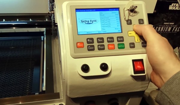
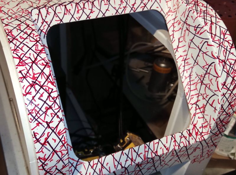
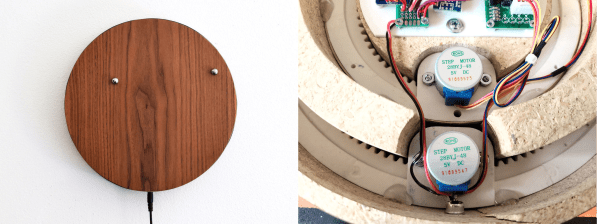
[tomatoskins] designed a DIY version that’s far more elegant. It has two ball bearings that move around the surface against hidden magnets — an hour ball and a minute ball. Inside there’s a pair of 3D-printed ring gears that are each driven by a stepper motor and controlled with an Arduino Nano and a real-time clock module. The body is made of plywood reclaimed from a bed frame, and [tomatoskins] added a walnut veneer for timeless class.

In addition to the code, STLs, and CAD files that birthed the STLs, [tomatoskins] has a juicy 3D-printing tip to offer. The gears had to be printed in interlocked pieces, but these seams can be sealed with a solution of acetone and plastic from supports and failed prints.

If you dig minimalism but think this clock is a bit too vague to read, here’s a huge digital clock made from small analog clocks.

What To Know When Buying Chips That Haven’t Been Made For Three Decades

Those of us who have worked with vintage sound generator chips such as the Yamaha FM synthesizers in recent years have likely run into our own fair share of “fake” or “remarked” chips, sometimes relabeled to appear as a chip different than the die inside the packaging entirely. [David Viens] from Plogue has finally released his findings on the matter after 3 years of research. (Video, embedded below.)

The first thing to determine is in what way are these chips “fake”? Clearly no new YM2612’s were manufactured by Yamaha in 2015, but that doesn’t mean that these are simply unlicensed clones put out by another die factory. [David] explains how these chips are often original specimens sourced from recycled electronic waste from mostly environmentally unsafe operations in China, which are then reconditioned and remarked to be passed as “new” by resellers. Thankfully, as of 2017, he explains that most of these operations are now being shut down and moved into an industrial park where the work can be done in a less polluting manner.

The next thing that [David] dives into is how these remarked chips can be spotted. He explains how to use telltale signs in the IC packaging to identify which chip plant produced them, and visible indications of a chip that has been de-soldered from a board and reconditioned. There are different ways in which the remarking can be done, and sometimes it’s possible to undo the black-top, as it’s called, and reveal the original markings underneath with the simple application of acetone with a cotton swab.

We’ve talked about fake chips and how they can lead to hardware failure here before, but in the case of chips like these which aren’t manufactured anymore, we’re not left with much choice other than FPGA or software reimplementations. Check out [David]’s 40-minute look into these chips after the break.

Continue reading “What To Know When Buying Chips That Haven’t Been Made For Three Decades”

Custom Control Panels With Photogrammetry

One of the best applications for desktop 3D printing is the creation of one-off bespoke components. Most of the time a halfway decent pair of calipers and some patience is all it takes to model up whatever part you’re after, but occasionally things get complex enough that you might need a little help. If you ever find yourself in such a situation, salvation might be just a few marker scribbles away.

As [Mangy_Dog] explains in a recent video, he wanted to model a control panel for a laser cutter he’s been working on, but thought the shapes involved were a bit more than he wanted to figure out manually. So he decided to give photogrammetry a try. For the uninitiated, this process involves taking as many high-resolution images as possible of a given object from multiple angles, and letting the computer stitch that into a three dimensional model. He reasoned that if he had a 3D model of the laser’s existing front panel, it would be easy enough to 3D print some replacement parts for it.

That would be a neat enough trick on its own, but what we especially liked about this video was the tip that [Mangy_Dog] passed along about increasing visual complexity to improve the final results. Basically, the software is looking for identifiable surface details to piece together, so you can make things a bit easier for it by taking a few different colored markers and drawing all over the surface like a toddler. It might look crazy, but all those lines give the software some anchor points that help it sort out the nuances of the shape.

Unfortunately the markers ended up being a little more permanent than [Mangy_Dog] had hoped, and he eventually had to use acetone to get the stains off. Certainly something to keep in mind. But in the end, the 3D model generated was accurate enough that (after a bit of scaling) he was able to design a new panel that pops right on as if it was a factory component.

Hackaday readers may recall that when we last heard from [Mangy_Dog] he was putting the finishing touches on his incredible “Playdog Blackbone” handheld gaming system, which itself is a triumph of mating 3D printed components with existing hardware.

Continue reading “Custom Control Panels With Photogrammetry”

Loads Of Testing Yields New, Reliable, And Cheap Leather Hardening Technique

Leather hardening has been around for such a long time that one might think that there was little left to discover, but [Jason F. Timmermans] certainly showed that is not the case. Right around the end of 2018 he set up experiments to compare different techniques for hardening leather, and empirically determine the best options. After considerable effort, he crafted a new method with outstanding results. It’s part of his exhaustive testing of different techniques for hardening leather, including some novel ones. It was a considerable amount of work but [Jason] says that he gathered plenty of really useful information, which we’re delighted that he took the time to share it.

According to [Jason], the various methods of hardening can be separated into four groups:

  1. Thermal: heat-treating at 180 ºF or higher, usually via some kind of boiling or baking process.
  2. Chemical: soaking in a substance that causes changes in the leather. Some examples include ammonia, vinegar, acetone, brine, and alcohol.
  3. Mechanical: hammering the leather.
  4. “Stabilizing” methods: saturating the leather with a substance to add rigidity and strength without otherwise denaturing the leather itself. Examples include beeswax, pine pitch, stearic acid, and epoxy.

We recommend making the time to follow the link in the first paragraph and read the full results, but to summarize: heat-treating generally yields a strong but brittle product, and testing revealed stearic acid  — which resembles a kind of hard, dense wax at room temperature — was an early standout for overall great results. Stearic acid has many modern uses and while it was unclear from [Jason]’s reasearch exactly when in history it became commonplace, at least one source mentioned it as a candidate for hardening leather.

But the story doesn’t stop there. Unsatisfied with simply comparing existing methods, [Jason] put a lot of work into seeing if he could improve things. One idea he had was to combine thermal treatment with a stabilizer, and it had outstanding results. The winning combination (named X1 in his writeup) was to preheat the leather then immerse it in melted stearic acid, followed by bringing the temperature of the combination to 200 ºF for about a minute to heat treat the leather at the same time. [Jason]’s observation was that this method “[B]lew the rest out of the water. Cutting the sample to view the cross section was like carving wood. The leather is very rigid and strong.”

The world may not revolve around leather the way it used to, but there’s still stuff to learn and new things to discover. For example, modern tools can allow for novel takes on old techniques, like using 3D printing to create custom leather embossing jigs.

Decap ICs Without The Peril

There can be few of us who haven’t gazed with fascination upon the work of IC decappers, whether they are showing us classic devices from the early years of mass semiconductor manufacture, or reverse-engineering the latest and greatest. But so often their work appears to require some hardcore scientific equipment or particularly dangerous chemicals. We’ve never thought we might be able to join the fun. [Generic Human] is out to change all that, by decapping chips using commonly available chemicals and easy to apply techniques. In particular, we discover through their work that rosin — the same rosin whose smell you will be familiar with from soldering flux — can be used to dissolve IC packaging.

Of course, ICs that dissolved easily in the face of soldering wouldn’t meet commercial success, so an experiment with flux meets little success. Pure rosin, however, appears to be an effective decapping agent. [Generic Human] shows us a motherboard voltage regulator boiled in the stuff. When the rosin is removed with acetone, there among the debris is the silicon die, reminding us just how tiny these things are. We’re sure you’ll all be anxious to try it for yourselves, now, so take a while to look at the video below showing their CCC Congress talk.

The master of chip decapping is of course [Ken Shirriff], whose work we’ve featured many times. Our editor [Mike Szczys] interviewed him last year, and it’s well worth a look.

Continue reading “Decap ICs Without The Peril”

RFID Payment Ring Made From Dissolved Credit Card

RFID payment systems are one of those things that the community seems to be divided on. Some only see the technology as a potential security liability, and will go a far as to disable the RFID chip in their card so that it can’t be read by a would-be attacker. Others think the ease and convenience of paying for goods by tapping their card or smartphone on the register more than makes up for the relatively remote risk of RFID sniffers. Given the time and effort [David Sikes] put into creating this contactless payment ring, we think it’s pretty clear which camp he’s in.

Alright, so the whole ring making part sounds easy enough, but how does one get an RFID chip that’s linked to their account? Easy. Just call the bank and ask them for one. Of course, they won’t just send you out a little RFID chip and antenna to mount in your hacked up project. (If only things were so simple!) But they will send you a new card if you tell them your old one is getting worn out and needs a replacement. All you have to do when it gets there is liberate the electronics without damaging them.

[David] found that an hour or so in an acetone bath was enough to dissolve the plastic and expose the epoxy-encased RFID chip, assuming you scrape the outer layers of the card off first. He notes that you can speed this part of the process up considerably if you know the exact placement and size of the RFID chip; that way you can cut out just the area you’re interested in rather than having to liquefy the whole card.

Once you have your chip, you just need to mount it into a ring. [David] has designed a 3D printable frame (if you’ve got a high-resolution SLA machine, that is) which accepts the chip and a new antenna made from a coil of 38 AWG magnet wire. With the components settled into the printed frame, its off to a silicone mold and the liberal application of epoxy resin to encapsulate the whole thing in a durable shell.

If a ring is not personal enough for you, then the next step is getting the RFID chip implanted directly into your hand. There are even folks at hacker cons who will do that sort of thing for you, if you’re squeamish.

Continue reading “RFID Payment Ring Made From Dissolved Credit Card”

Component Shelf Life: How To Use All That Old Junk

There are two types of Hackaday readers: those that have a huge stock of parts they’ve collected over the years (in other words, an enormous pile of junk) and those that will have one a couple of decades from now. It’s easy to end up with a lot of stuff, especially items that you’re likely to use in more than one design; the price breakpoints at quantities of 10 or 100 of something can be pretty tempting, and having a personal stock definitely speeds the hacking process now that local parts shops have gone the way of the dinosaur. This isn’t a perfect solution, though, because some components do have shelf-lives, and will degrade in some way or another over time.

If your stash includes older electronic components, you may find that they haven’t aged well, but sometimes this can be fixed. Let’s have a look at shelf life of common parts, how it can be extended, and what you can do if they need a bit of rejuvenation.

Continue reading “Component Shelf Life: How To Use All That Old Junk”