BeagleBone Black Becomes A Handheld Classic Gaming Console

Over at TI, the 2013 Intern Design Challenge is underway, an opportunity for the interns of TI to flex their engineering muscle for a few prizes and a chance to have their designs turned into actual products. We’re thinking [Max] might just pull this one out with his BeagleBone Gaming Cape, an add-on to the BeagleBone Black that turns this ARM-powered Linux board into a retro gaming system.

The build was inspired by [Max]’s earlier MSP430 Launchpad GamingPack, an add-on board for the Launchpad that put two NES controllers, a VGA out, and an FPGA to create a custom gaming console that’s up there with the brightest and best consoles of the 16-bit era. For the new BeagleBone-based build, [Max] eschewed off-board processing, but did manage to include a magnetometer/accelerometer and an audio codec IC to provide the best gaming experience for all those NES, Game Gear. Gameboy, GBA and Doom .wad games.

In addition to a fabulous piece of hardware, [Max] also has the case design down to a tee. He first printed out a dozen or so layers of his case, sandwiching the BeagleBone, his cape, battery holders, and LCD display. Once he knew the dimensions would work, he sent his files off to be laser cut out of a matte black delrin. The finished piece is a work of art, and considering how well everything goes together, we wouldn’t mind giving this new retro-gaming console a spin ourselves.

Turn Your BeagleBoneBlack In To A 14-channel, 100Msps Logic Analyzer

The BeagleBoneBlack is a SoC of choice for many hackers – and quite rightly so – given its powerful features. [abhishek] is majoring in E&E from IIT-Kharagpur, India and in 2014 applied for a project at beagleboard.org via the Google Summer of Code project (GSoC). His project, BeagleLogic aims to realize a logic analyzer using the Programmable Real-Time units on board the AM335X SoC family that powers the BeagleBone and the BeagleBone Black.

The project helps create bindings of the PRU with sigrok, and also provides a web-based front-end so that the logic analyzer can be accessed in much the same way as one would use the Cloud9 IDE on the BeagleBone/BeagleBone Black to create a new application with BoneScript.

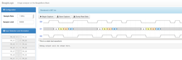
Besides it’s obvious use as a debugging tool, the logic analyzer can also be a learning tool that can be used to understand digital signals. BeagleLogic turns the BeagleBone Black into a 14-channel, 100Msps Logic Analyzer. Once loaded, it presents itself as a character device node /dev/beaglelogic. In stand-alone mode, it can do binary captures without any special client software. And when used in conjunction with the sigrok library, BeagleLogic supports software triggers and decoding for over 30 different digital protocols.

The analyzer can sample signals from 10Hz upto 100MHz, in 8 or 16 bits and up to a maximum of 14 channels. Sample depth depends on free RAM, and upto 320MB can be reserved for BeagleLogic. There’s also a web interface, which, once installed on the BeagleBone, can be accessed from port 4000 and can be used for low-volume captures (up to 3K samples).

[abhishek] recently added the BeagleLogic Cape which can be used to debug logic circuits up to 5V safely. Source files for BeagleLogic as well as the Cape are available via his github repos. [abhishek] blogged about his project on his website where there’s a lot more information and links to be found. Catch a video of BeagleLogic after the break.

Continue reading “Turn Your BeagleBoneBlack In To A 14-channel, 100Msps Logic Analyzer”

This BeagleBone’s Got AI

There are a lot of BeagleBones, from Blue, to White, Green, Black, and we think there’s a purple one in there for some reason. The diversity of BeagleBones is due to the openness of the design, and is the biggest advantage over the ‘bone’s main competitor, the Raspberry Pi.

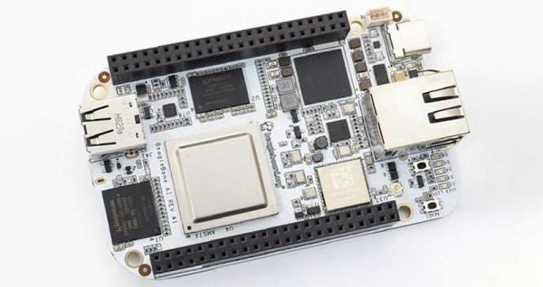
Now, there’s a new BeagleBone, and this time the color is AI. The BeagleBoard foundation has just unveiled the BeagleBone AI, and it is going to be the most powerful BeagleBone ever developed.

Unlike the BeagleBone Blue, Black, or the PocketBeagle, the BeagleBone AI uses the TI AM5729 processor, a dual-core ARM Cortex-A15 running at 1.5 GHz. It’s not a BeagleBone unless it has those nifty real-time programmable units, and yes, this one has four. This is the BeagleBone AI, so something else has to be different, and it comes with four Embedded Vision Engines (EVEs), a TIC66x DSP, and support for machine learning with pre-installed tools.

Of especially interesting note, this board features USB C connectors, Gigabit Ethernet, onboard WiFi, 1 GB of RAM, and 16 GB of eMMC Flash. The massive block of pin headers remains the same.

If this feature set sounds somewhat familiar to the Beagle family, you’re right. The BeagleBoard X-15 — the alpha wolf of the BeagleBone family — also comes with DSP, and Cortex-A15 cores running at 1.5 GHz. The use case for the X-15 was a little puzzling, as it was too big to really be a portable or embeddable system, but didn’t have the power of the likes of an Nvidia Jetson or what have you. The BeagleBone AI is essentially a minified version of the X-15, albeit slightly less capable in terms of RAM and Flash.

An Even Smaller BeagleBone

The BeagleBone famously fits in an Altoids tin. Even though we now have BeagleBone Blacks, Blues, and Greens, the form factor for this curiously strong Linux board has remained unchanged, and able to fit inside a project box available at every cash register on the planet. There is another Altoids tin, though. The Altoid mini tin is just over 60×40 mm, and much too small to fit a normal size BeagleBone. [Michael Welling] has designed a new BeagleBone to fit this miniature project box. He’s calling it the Pocketbone, and it’s as small as the mints are strong.

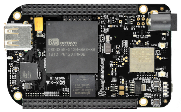
The Pocketbone is based on the Octavo Systems OSD355x family, better known as the ‘BeagleBone on a chip’. This chip features a TI AM355x ARM Cortex A8, up to 1GB of DDR3 RAM, 114 GPIOs, 6 UARTs, 2 SPIs, 2x Gigabit Ethernet, and USB. It’s housed in a relatively large BGA package that makes routing easy, and as a proof of concept [Jason Kridner] built a PocketBone in Eagle.

[Michael]’s version of the Pocketbone is based on the earlier proof of concept, with a few handy additions. There’s an IO expansion header, provisions for a battery input, a few fixes to the USB, and all the parts are on one side of the board facilitating easier assembly. This version of the Pocketbone was created using KiCad, which will endear the project to the Open Source community.

New Part Day: Wireless BeagleBones On A Chip

The BeagleBone is a very popular single board computer, best applied to real-time applications where you need to blink LEDs really, really fast. Over the years, the BeagleBone has been used for stand-alone CNC controllers, the brains behind very large LED installations, and on rare occasions has been used to drive CRTs. If you just want a small Linux board, get a Pi. If you want to do something interesting with hardware, get a BeagleBone.

The BeagleBone ecosystem has grown a lot in the last year, from the wireless and Grove connector equipped BeagleBone Green, the robotics-focused BeagleBone Blue, the Zoolander-inspired Blue Steel. Now there’s a new BeagleBone, built around a very interesting System on Module introduced earlier this year.

The new board is called the BeagleBone Black Wireless, and it brings to the table all you know and love about the BeagleBone. There’s a 1GHz ARM355x with two 32-bit 200MHz PRUs for the real-time pin toggling. RAM is set at 512MB, with 4GB of eMMC Flash and Debian pre-installed, and a microSD card for larger storage options. The new feature is wireless connectivity: a TI WiFi and Bluetooth module with provisions for 802.11s replaces the old Ethernet connector.

Taken at face value, the new BeagleBone Black Wireless deserves a mention — it’s a BeagleBone with wireless — but isn’t particularly noteworthy. But when you get to the gigantic brick of resin dropped squarely in the middle of the board does the latest device in the BeagleBone family become very, very interesting. The System on Module for this version of the BeagleBone is the BeagleBone On A Chip released a few months ago. The Octavo Systems OSD335x is, quite literally, a BeagleBone on a chip. It’s a BGA with big balls, making it solderable with hand-applied solder paste and a toaster oven reflow conversion. In fact, the BeagleBone Wireless was designed by [Jason Kridner] in Eagle as a 6-layer board. It’s still a bit beyond the standard capabilities of OSHPark, but the design can still be cut down, and shows how this BeagleBone on a Chip can be applied to other Open Hardware projects.

[Ken Shirriff] Demystifies BeagleBone I/O

If you have ever spent a while delving into the bare metal of talking to the I/O pins on a contemporary microprocessor or microcontroller you will know that it is not always an exercise for the faint-hearted. A host of different functions can be multiplexed behind a physical pin, and once you are looking at the hardware through the cloak of an operating system your careful timing can be derailed in an instant. For these reasons most of us will take advantage of other people’s work and use the abstraction provided by a library or a virtual filesystem path.

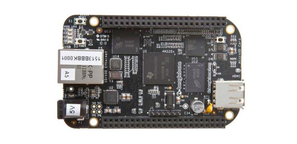
If you have ever been curious enough to peer under the hood of your board’s I/O then you may find [Ken Shirriff]’s latest blog post in which he explores the software stack behind the pins on a BeagleBone Black to be of interest. Though its specifics are those of one device, the points it makes have relevance to many other similar boards.

He first takes a look at the simplest way to access a Beagle Bone’s I/O lines, through virtual filesystem paths. He then explains why relying so heavily on the operating system in this way causes significant timing issues, and goes on to explore the physical registers that lie behind the pins. He then discusses the multiplexing of different pin functions before explaining the role of the Linux device tree in keeping operating system in touch with hardware.

For some Hackaday readers this will all be old news, but it’s safe to say that many users of boards like the BeagleBone Black will never have taken a look beyond the safely abstracted ways to use the I/O pins. This piece should therefore provide an interesting education to the chip-hardware novice, and should probably still contain a few nuggets for more advanced users.

We’ve seen a lot of [Ken]’s work here at Hackaday over the years, mostly in the field of reverse engineering. A few picks are his explanation of the TL431 voltage reference, a complete examination of the 741 op-amp, and his reverse engineering of the 1970s Sinclair Scientific calculator.

We appreciate [Fustini]’s tip on this story.

BeagleBone Black image: BeagleBoard.org Foundation [CC BY-SA 3.0], via Wikimedia Commons.

Blindingly Fast ADC For Your BeagleBone

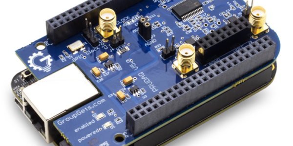
[Jason Holt] wrote in to tell about of the release of his PRUDAQ project. It’s a dual-channel 10-bit ADC cape that ties into the BeagleBone’s Programmable Realtime Units (PRUs) to shuttle through up to as much as 20 megasamples per second for each channel. That’s a lot of bandwidth!

The trick is reading the ADC out with the PRUs, which are essentially a little bit of programmable logic that’s built on to the board. With a bit of PRU code, the data can be shuttled out of the ADC and into the BeagleBone’s memory about as fast as you could wish. Indeed, it’s too fast for the demo code that [Jason] wrote, which can’t even access the RAM that fast. Instead, you’ll want to use custom kernel drivers from the BeagleLogic project (that we’ve covered here before).

But even then, if you don’t want to process the data onboard, you’ve got to get it out somehow. 100 mbit Ethernet gets you 11.2 megabytes per second, and a cherry-picked flash drive can save something like 14-18 megabytes per second. But the two 10-bit ADCs, running full-bore at 20 megasamples per second each, produces something like 50-80 megabytes per second. Point is, PRUDAQ is producing a ton of data.

So what is this cape useful for? It’s limited to the two-volt input range of the ADCs — you’ll need to precondition signals for use as a general-purpose oscilloscope. You can also multiplex the ADCs, allowing for eight inputs, but of course not at exactly the same time. But two channels at high bandwidth would make a great backend for a custom SDR setup, for instance. Getting this much ADC bandwidth into a single-board computer is an awesome trick that used to cost thousands of dollars.

We asked [Jason] why he built it, and he said he can’t tell us. It’s a Google Research project, so let the wild conjecture-fest begin!