The latest and greatest feature for 3D printers – besides being closed source, having no meaningful technical specs, and being on track towards pulling in $10 Million on a Kickstarter – is automated bed leveling. This amazingly useful feature makes sure your prints have proper adhesion to the bed, reduce print errors, and put even inexpensive printers into the realm of extremely expensive professional machines. Automated bed leveling has been extremely hard to implement in the past, but now [Scottbee] has it figured out with a working prototype on his Makerbot Replicator 2X.
Earlier attempts at automated bed leveling used some sort of probe on the tool head to measure the build plate, calculate its flatness and orientation in space, and compensate for any tilt in software. [Scottbee]’s solution to the problem took a different tack: instead of trying to compensate for any odd orientation of the build surface in software, he’s simply making the bed level with a series of springs and cam locks.
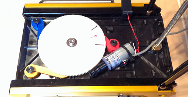
[Scottbee]’s device levitates the build plate on three springs, and replaces the jack screws with three “gimballing pins” and pin locks. With the pin locks disengaged, the bed plate is pressed down with the printer’s nozzle. By moving the extruder across the build plate and locking the pins in place one by one, [Scottbee]’s device defines the plane of the build plate along three points. This makes the build platform parallel to the extruder nozzle, and also has a nice benefit of setting the distance from the build platform to the nozzle precisely with incredible repeatability.
The mechanics of locking the three gimballing pins in place only requires a single DC gear motor, driven by an extra fan output on the Makerbot’s electronics. It’s simple, and with a bit of rework, it looks like most of the device could also be 3D printed.
An awful lot of RepRaps and 3D printers out there already use three points to attach the build plate to a frame. With a little bit of effort, this same technique could be ported and made a bit more generic than the Makerbot-based build seen above. It’s amazingly simple, and we can’t wait to see this applied to a normal RepRap.
Thanks [Josh] for the tip.


“and put even inexpensive printers into the realm of extremely expensive professional machines”
Not quite.
Yes. For similar print volume, depending on what figures are meant for “extremely expensive professional machines”, those pro machines quickly leave fused filament technology.
The article shows an interesting solution, but I think the effort is better spent in building a higher quality, more passive means of assuring a level bed.
exactly, leveling the bed should be one-time operation. Unless of course you build it from card board and chewing gum
I guess I just don’t see it. It seems too complicated and unncessarily adds to the cost of the platform.
The print head already moves in 3d space. It just needs offsets to compensate for alignment issues in both the bed and also the frame/gantry. That is one of the problems with the mechanical bed approach – it does not solve the other alignment issues.
Surely there are benefits to having a level bed relative to the X-Y over compensating for the slant. I… I just can’t come up with any that don’t involve things being *way* slanted. Hmm…
I’d much rather have a level platform to print on instead of moving z in conjunction with x and y. That will only introduce another source for print quality degradation. Adding the z-axis to all printing moves will also increase noise of the machine.
When entering the realm of dual extruder, quad extruder, etc. Software compensated bed leveling just does not work. Once you swap to any of the other extruders, if your bed isn’t completely level you’ll end up dragging or diving your other nozzles into the print.
In the world of real CNC machining, that is solved by “indexed tooling”. Each cutting tool is in a holder and is adjusted so the cutting point contacts a specific 3d point reference. So when tooling is changed, the index is maintained.
But if your print head isn’t completely straight and level, then mechanically leveling the bed relative to one of the nozzles won’t help you because the other nozzles will still be at different heights and angles and you still have the exact same problem.
Bed leveling cannot compensate for a skewed frame. If your Z axis is not perpendicular to your XY plane (MOTION plane, NOT the bed plane), then your prints WILL be skewed regardless of software or hardware bed leveling.
Nice. But does not compensate for a warped build platform.
I envisage a multi point reading of the surface followed by the deposition of a compensating layer.
The issue, naturally is the sensor, and its relation to the nozzle. Solution.. add a miniature cellphone vibrator to the extruder and a microphone to the build surface. Soem basic electronics and you will be able to tell if the nozzle is touching the build platform.
It doesn’t, but why would you not replace a warped platform? Seems kind of silly to adjust for something like that in software instead of buying a properly flat surface to print on in the first place.
Cost of the properly leveled surface.
Buy a block of [whatever]. Go to an automotive place that resurfaces warped engine heads. Pay them $50 to cut a large, perfectly smooth, level surface with their expensive resurfacing machine.
And whatever sensor(s) and other hardware you need is free? A nice piece of flat glass isn’t expensive and if you can afford all the bits for a 3d printer, a few extra bucks isn’t going to be a problem now is it?
Super cheap sheet of picture frame glass? It’s not that hard.
Nothing is perfectly flat. Some commonly available materials may be adequately flat. All that being said… microphones are incredibly cheap and effective, as are cellphone vibrators.
You can float your 3D printer on water. Surface of a liquid will always be level (that’s how inertial navigation in Tu-154M planes worked)
Problem is not to have whole printer leveled against earth. Problem is to have bed leveled against nozzle… So if you are moving nozzle along X and Y it does not change it’s distance (Z) from bed.
it has to be level relative to the printhead though. and you can’t exactly float that on water.
Wouldn’t the center of gravity (and thus the tilt) change as the filament builds up?
A probe is helpful for calibrating other things besides the bed height and tilt, especially on a delta.
Regarding automated bed leveling & calibration, you might want to check this system out (much much simpler): http://reprap.org/wiki/FSR, https://www.youtube.com/watch?v=HcnhCNh2Ln4, https://groups.google.com/forum/#!topic/deltabot/SrmxHMxdgBE. Tons of more info here: https://groups.google.com/forum/#!topic/deltabot
Does that system actually level the bed, or does it just find the plane and adjust in software? I’ve seen a servo driven “leg” for the extruder on the prusa that works to the same end. For a deltabot as you’ve linked, having an unlevel plane probably doesn’t matter as much for build quality.
The whole point of this approach was to NOT use sensors or switches and then use software to compensate.
Yeah, we’ve seen it before, and there are some problems associated with it.
Force sensitive resistors are only good up to about 70 degrees C, so that means no heated bed. Also, the FSR technique only *compensates* for an unlevel bed in software. It doesn’t actually level the bed like the build here.
I like the idea of physically leveling the bed rather than doing compensations in software. We’ve seen the crazy 30° angled bed demos; Nifty, but how realistic is that? Heh, who has a bed that is that obviously un-aligned? I know it’s just an extreme demo, but I feel like software compensation will introduce more Z-axis backlash into the print.
I don’t see how the 3-point probe would compensate for a warped build plate either, so that point is kinda moot. I’m sure a “continuous” reading of the bed’s surface is technically possible…but why go through the effort to make up for a shitty warped bed to begin with? I would approach that problem by getting or making a bed that won’t warp in the first place. Maybe easier said than done? I have a Felix 3D printer with aluminum sandwich bed which supposedly warps when heated, but I don’t seem to have any issues with mine. Yet. :D
Come on guys! This is simple and elegant, kudos to Scottbee! What I’m wondering about is intellectual property rights. I am curious now if there is a patent equivalent to the GPL {goes of to google “open source hardware”}
Man, for all the nay-sayers, I haven’t heard a suggestion yet that gives the same end result as the article’s system does: an actual level bed, not compensation for an unlevel bed. As for those complaining about how it doesn’t work for warped beds, what simple thing does in 10 seconds? And why would you want to print on a warped bed anyway?
Its not automatic, but I just have spring backed bolts on the corners of my plate. It only took a few minutes to get it level relative to the print head.
As a side note my played is warped slightly, only because I put a spring in the middle to keep the heater PCB tight against the glass. But it doesn’t cause much of a problem
I’ve had good luck flattening out my bed using a cheap dial indicator from Harbor Freight. Oldschool and highly effective.
I’ve often wondered why print heads don’t have the facility for fitting a DTI. It’s such an obvious solution.
I’ve done that a couple different ways. One was an indicator mount that bolts to the extruder mount, where you remove the extruder and mount the indicator. The other is I added a way to mount the indicator on the carriage as close to the hot end as I can fit it.
I think I understand the solution, and it seems to be a pretty clever solution, but I need a few more tries at it.
It would be nice to see the underside of the cam, which can explain how each pin gets locked down. The “gimbal pins” look like ordinary flat head screws.
How does the system home the cam wheel?
Can someone explain, how the machanism works with just one motor?
At various points on that big gear, the three cam followers are either loose or tight on the mounting rods. Therefore, as the gear turns, the rods will loosen or tighten in a repeatable sequence. Just make sure the nozzle is in the right place for each of those events.
Simply build the printer and platform out of materials rigid enough to stay square and level, and manufacture them so they assemble together with everything square and level. That’s why the printer I’m collecting parts for will have a frame of 4040 T slot extrusion with joints connected by both the end connectors *and* angle brackets. I may triple up the rigidity with triangular gussets just to be certain there will be no movement.
Very similar to a tribrach from a total station. http://www.surveyequipment.com/surveying-accessories/tribrachs/leica-gdf112-basic-tribrach-with-optical-plummet#.U05M8fldVSM
3 point leveling at the twiddle of some knobs!
Dude this sound like a great device. Can you make it to fit a xyz davinci there leveling system sucks monkey b.ll.ks