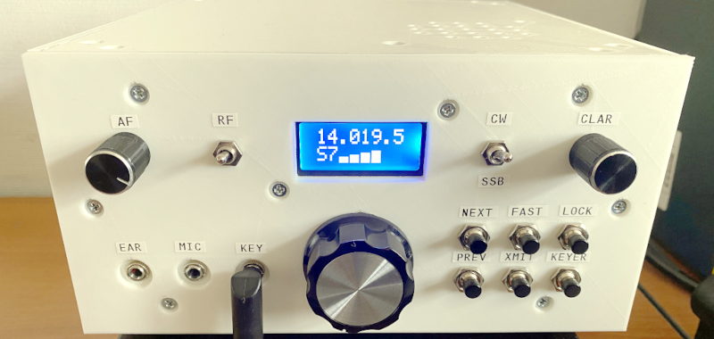
[Alex R2AUK] has been busy creating version two of a homebrew all-band ham radio transceiver. The unit has a number of features you don’t always see in homebrew radios. It covers the 80, 40, 30, 20, 17, 15, 12, and 10 meter bands. The receiver is a single-IF design with AGC. The transmitter provides up to 10W for CW and 5W for single sideband operations. There’s a built-in keyer, too. A lot of the documentation is in Russian (including the video below, which is part of a playlist). But translation tools are everywhere, so if you don’t speak Russian, you can still probably figure it out.
The VFO for both transmit and receive is an Si5351. The transmit chain is straightforward. The receiver reuses many of the same filters.
Like many projects these days, an attractive 3D-printed case gives the radio a polished look. If you prefer using a straight key to a keyer, the transmitter will use either. The microphone amplifier has built-in compression for good audio levels.
If you don’t want to roll your own, you can get similar ham gear that is ready-built. If you want to go minimal. we’ve seen a less-capable transceiver built with only seven transistors.


Is possible send/receive digital data too?
for example mesh network?
speed more than DMR or wifi 7
Digital data sent over HF is merely a specially formed SSB. Only some software (WSJT-X, Fldigi, …) and a specialized USB sound card to interface with the transceiver are required (e.g. SignaLink). Personally I find SignaLink a little bit overpriced so I ended up building my own digital mode interface. It is described in the article “Самодельный интерфейс для работы в цифровых видах связи” which can be easily found by the title. Google Translate will translate it for you if needed.
There’s also DRM, Digital Radio Mondiale.
It can be received by a Direct Conversion (DC) receiver and a sound card, but not by an unmodified SSB receiver (needs IF tap).
The IF bandwith has to be 7 KHz at minimum (12, ideally).
Back in late 2000s, DReaM software was popular to decode it.
While the technology was meant for replacing commercial AM broadcast on shortwave, it also existed as a ham version.
Special versions of Dream for ham use existed.
existed != on github
we talking about this project not every project in galactic
God bless hams for going ‘yea that’s a bit overpriced… I’ll make my own.’
And then doing it.
Nicely done. That tuning knob looks like it came right off of my Ten-Tec Omni-D.
Nice and clean looking. But can we learn to use something other than the Si5351?? It looks like every rig must start with a 5351—Borrrring!
As someone who wrote an STM32 driver for Si5351 from scratch I disagree that its boring :)
I tried other options like AD9850 and they are worse – the signal has more noise and the price is higher. Si5351 is a good option in terms of price/quality, this is why it was chosen in this project. BTW note that BFO is analog. In my experience using Si5351 for both VFO and BFO creates too many spurs. This is because the signal from Si5351 is far from being a true square wave.
If you know better options than Si5351 please let me know.
Isn’t the Si570 cleaner, especially as to fractional spurs? Yes, a little more expensive. How about a well designed, stabilized LC?
I have no problem (been there, done that) doing the programming – not bad. Done it also with a PIC to lessen the EMI that I experienced with Arduino. The issue is a part that is sole-sourced ( other than a recent, new source). Completely unobtainium for an inordinately long time during and after the pandemic.
Very Nice effort on this rig in all other respects! It does look nice and ready for portable operation
Well it’s all about compromises, right?
Si570 doesn’t seem to be easily obtainable worldwide and I wanted this project to be as reproducible and repairable as possible.
I used LC circuits before. It is a good choice in a rig for 1 or 2 bands. However I wanted to cover 8 HF bands in this project and wanted to fit everything in a relatively small enclosure. I ended up using 0805 SMD components in order to achieve this and even so the project was a challenge for me.
All in all I think Si5351 was a good compromise in this particular case. This being said, it’s open-source. Feel free creating a fork and using VFO you personally prefer. All you are going to need is replacing the “Digital” PCB, the rest 7 PCBs can be left as is.
Thanks for your nice words and 73s!
Can you even do interesting RF stuff with passives and RF BJTs without a VNA and spectrum analyzer?
It’s going to be less convenient but you can. I’m using a fancy* spectrum analyzer because besides other things it can save screenshots. Since I’m a blogger it save me a lot of time when it comes to writing articles. You can use a more affordable NanoVNA (check out Nooelec store) or even an oscilloscope with inexpensive signal generator (e.g. MHS-5200A). I used simpler equipment in the past – it gave me same results, just took more time.
As the designer of the minimalist less capable 7 transistor radio, I can well appreciate what is behind your front panel. Well done!
There is nothing boring about a Si5351 and it is all a matter of cost, capability and availability. For more demanding applications certainly there are products around.
N6QW
Thanks, Pete.
Did you recognize one of your circuits in the project? The driver for TDA2003 is yours, from PSST. Previously I used op-amps for this purpose but discovered that they add much low-frequency noise to the signal. So I did a quick look for a driver on a single NPN transistor and found yours. I realize it’s merely a LF common-emitter amplifier but I didn’t want to do the math and also wanted a circuit already used in a real-world transceiver. I used smaller values for the capacitors in order to fit everything into the space I had.
So thanks for your contribution! :)
The Si5351 availability has improved – a good sign. And so has the other source’s availability. As one of its prime applications is automotive clock trees, we may see this to improve and possibly add other sources, in a hot market. This makes our design-in process much easier.
Thanks for making your project Open-Source. When someone forks your project, adds a little innovation, and comes up with something with new features, its very cool.
Okay you know that the international organization wants us to start using our gigahertz band with allocations so we should start building sdrs with gigahertz band capabilities and examining our local laws and regulations on how we can use either satellites or a mesh system and repeaters or directional antennas as these bandwidths have low penetration but high bandwidth capabilities but you have to increase the power or have short distances and line of sight but we need to use them we’re going to lose them!
Want to bet it works on 10M too?
Yes, if the software allows it, “10m” (Citizen Band aka 11m) will also work. ;)
Though at least were I live, 12W is being used for SSB. And 4W for AM/FM on first 40 CH.
So this little guy could need a upgrade. A cute little linear, maybe? Would be another nice project for these QRP boxes.
Yes it will work on CB. All you need is modifying the firmware just a bit and one of the band-pass filters.
All bands? No mention of 2 meter?
To clarify, this rig supports 8 HF bands: 80, 40, 30, 20, 17, 15, 12, and 10 meters. It will not work on other bands, at least not without a transverter. On top of that if you are not in IARU Region 1 your HF bands may differ and you may need to modify the firmware a bit. E.g. 40 meters in R1 are 7.0 – 7.2 MHz, while in R2 7.0-7.3 MHz.
Hi, there are transverters for this purpose.
10m to 2m is popular, because both are 2 MHz in size (10m: 28-30 MHz 2m: 144-146 MHz). Well, in IARU-1 region, I mean.
In the Americas, IARU-2 region, the 2m band is 4 MHz (144-148 MHz) so HF transceivers may need to support going up to 32 MHz.
In the past, some shortwave receivers had a 6m and 2m converter built-in.
Yaesu FR-101D, for example.
The use of transverters seems cumbersome first, but it’s not bad at all.
With an HF rig and a transverter you get a very sensitive receiver and SSB capability, for example.
And especially 10m band rigs have AM, FM and SSB, which is nice for working on 2m band.
Very cool
Well, i like such projects. I don’t like comments who just want to blame. If someone want to have an extension, because this version not gains the requirement, just do it. This project is open and any you need is time and the ability to do things like that. In most cases, for the blamers, it is impossible doing things like that. My congrats and i agree with Mike Hoppers short words: “Very Cool”.
Thanks for sharing…