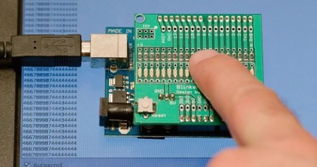
[Udo] figured out how to turn a bunch of LEDs into a very low resolution camera.
The build is based around [Udo]’s Blinkenlight shield he’s been developing over the past year. The camera operates under the idea that there’s really not much difference between a LED and a photodiode; LEDs can do light emission and detection. In actuality, the LED ‘camera’ isn’t all that different from a linear CCD array, the type of image sensor in flatbed scanners.
After connecting his Blinkenlight shield to his Arduino and computer, [Udo] wrote a sketch that would capture 17 values from his LED camera. These values are shot over the serial connection where high levels of light show up as smaller numbers and low light levels are understood as larger numbers.
[Udo] has been doing a lot of other cool stuff with his Blinkenlight shield, like a persistence of vision experiment and pretending to be [Michael Knight]. Check out the video after the break for a demo of [Udo]’s linear LED camera.
[youtube=http://www.youtube.com/watch?&v=3unSMko8m4Q&w=470]


Common, very common in robotics circles. easier to make a Linear optical array sensor like that than trying to use a silly camera.
Also brunswick does this for pin detection on bowling lanes. there is a location where you can see all pins on 2 lanes, they count the pins using a lineral optical detector like that.
This reminds me of the (very) old days of using UV-eprom chips at the focal point of a lens to build lo-res cameras.
EPROMS normaly would be unsuitable for a camera or sensor as they would hold their charge for a VERY long time. The trick I think you are talking about was the one where you hacked off the top off the old ceramic packaged RAM chips and stuck a microscope slide cover over to prevent oxidation. You could then set the memory values and then read them back when they changed they had seen enough photons ;). The time would give you an indication of the strength of the incident light. Did this with a ZX Spectrum and a bunch of 4164’s. The old Nintendo cameras are similar if I remember right.
That is fascinating I’d never heard of that trick. Thanks!
My point is not that I can implement a camera (or sensor). This is just one of many experiments.
Look here for more:
http://blog.blinkenlight.net/experiments/
All of them have been done before. Everything that is not cutting edge science has been done before. The question is if it has been documented in a convenient way.
BTW: did you check out the “power grid monitoring experiment”?
Well I never knew you could do this, yes I am stupid, so thanks for the demo.
Respectfully the power grid monitor would be more interesting if one where using a chart recorder application to plot the data so one can examine the results over time, at our leisure. To sit or stand watching a line frequency meter is what a power plant employee is paid to do, the rest of use are being nosy, or curious to put a nice sounding spin to our activity :) Thanks for sharing your project information.
It wouldn’t be to hard to implement an FFT, put out the results through serial and connect it to Nagios or something similar. But this would defer the point that I try to experiment with this shield. Actually if you want to monitor with a computer this is already done and the output is available online. I already mention this in my page including the link.
> the LED ‘camera’ isn’t all that different from a
> linear CCD array
damn, so now im wondering if I could light CCD camera “leds”, preferably more than once :)
pinhole camera’s have no lens, they still make pictures. And technically each LED has a plastic lens, the actual diode is only the small bit in there.
computer vision so simple that even a stupid arduino can understand it!
cool science expierment, could add a LED-matrix(graph) to it but this still looks cool for a live view, maybe show both on seperate displays
Also, led + crystal earphone = ir remote tester
Looks like a first step in the direction of optical camouflage if you ask me.
Just an idea but what about a spinning POV sensor? Instead of LED’s use photo transistors.
Send the signal through a tuned coil to avoid signal loss? Might be possible with a bit of tinkering.
If you like my experiments, please support me by voting for me at the buildounge laser cutter contest. It takes only one 1 minute of your time and 3 clicks. Just navigate to the page, click my entry (3rd from the top), scroll down and click the vote button.
Udo,
How do you get an Arduino to recognise whether the LEDs are ‘seeing’ dark or light? I presume you’re using the analogue inputs but what is your code?