While the Raspberry Pi has very good support for an I2C bus, a lot of very cool chips – including the in system programmer for just about every ATtiny and ATmega microcontroller – use an SPI bus. [Louis] sent in a tutorial for getting hardware SPI on his Raspi, and even though it’s rather limited right now, it’s a step in the right direction.
Previously, [Brian Hensley] put up a tutorial for using the Linux SPI drivers with the Raspi. [Louis] wanted to play with SPI in Python, so he added a C extension to the spidev.c file (available here) that allows him to open an SPI connection, initialize, transfer, and close the connection.
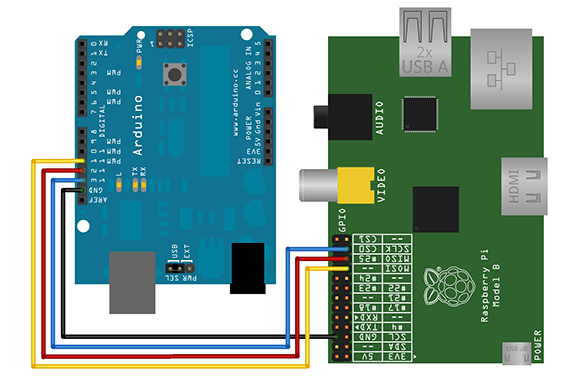
After connecting an Arduino to the MOSI, MISO and SCK pins of his Arduino, [Louis] was able to transfer data from his Raspi over an SPI bus. It should be noted that a level shifter would be a really good idea here, but this is an excellent project if anyone would ever want to port AVRDude to Python.


At first I thought this post was saying the drivers most people were using weren’t the hardware drivers but were the bit bang drivers. It looks like that’s not the case. I think this Python module will be very useful to a lot people.
Well he’s missing using a GPIO line from the raspberry Pi to pull the RESET line on the ICSP interface low.
Implementing that (and the obvious level converter) then you could make a “shield” for the Pi to program most AVR’s out there, either by plugging them into DIP sockets, or a 6pin and a 10pin ICSP header.
Forgot to to add:
Can one of the GPIO lines on the Pi be used to generate a clock signal for the AVR to use, instead of a crystal or resonator?
http://www.piborg.org has some SPI drivers for the Raspberry Pi – it’s for their board, but none the less quite useful open source stuff
Wrong image
You can NOT join arduino pins with raspberry pi pins directly, they use different voltage levels and you will break the rapsberry ones.
The Adafruit modified version of Raspbian comes with hardware SPI and I2C support: http://learn.adafruit.com/adafruit-raspberry-pi-educational-linux-distro/overview
As far as I could tell from documentation, their SPI and I2C support enables the hardware which is the first half of my tutorial, which is just a summary of Brian’s tutorial.
I wanted to access hardware SPI from Python and this was the easiest way for me figure out how to do it…
As far as I could tell, their distribution voids the first half of the tutorial which is based off of what Brian did.
The second half is about making that hardware accessible to Python with the C extension.
Why can’t somebody combine an Arduino + rPi on one board?
This is pretty close. An AVR and ARM in the same device – both removable.
http://www.seeedstudio.com/depot/dragrove-generic-gateway-for-internet-of-things-p-1118.html
Gordon’s modifications to avrdude for RPi can already program AVRs using SPI, +3V3 and GND. Check out this blog – https://projects.drogon.net/raspberry-pi/gertboard/arduino-ide-installation-isp/.
You can use the FTDI chips to do USB-SPI and USB-I2C. Just saying…
What’s your point? More hardware?
So how does this work without a level shifter? Isn’t this likely to damage the Raspi?
Isn’t this likely to damage the Raspi without a level shifter or current limiting resistors?
Note that Atmega8 and Atmega168 can run on 3.3V so problem with power levels is solved.
Yes, but the average Arudino user doesn’t know what any of that means… or that their precious Arduino is just packaging around said microcontrollers.
The example shows connecting an RPi directly to an Arduino, which runs on 5V. So while an Atmega can run at 3.3, that doesn’t really address the issue here. It may be posible to use current limiting resistors (not shown in the above diagram) to prevent damage to the RPi. Without that, you risk permanent damage to the RPi if you try to transfer data FROM the Arduino.
You could use a limiting resistor IF you know the current on the line. How could you calculate a voltage drop to achieve 3.3V on the line?
Better solution is to use zener diode which would ensure 3.3V
The idea is to prevent damage to the RPi. The Arduino has a limited output current. Start with an obviously too large R (like 4.7k?) and measure the voltage at the RPi pin. Lower the R until it gets to 2.5, enough to reliably toggle the RPi input pin. Simple and effective. Or use 2 R’s as a divider. There is a discussion of both methods here:
http://www.raspberrypi.org/phpBB3/viewtopic.php?f=45&t=22841
Some Arduinos run at 3.3V (e.g. the Arduino Pro Mini 3.3V). If you use one of these then you won’t need a level shifter. If you use a ‘normal’ Arduino (e.g. Uno) then you will get the Raspi a bit upset and probably break it quite comprehensively.