[Afroman] is back again with another great tutorial video on the basics of electronics. This time it’s zener diodes.
Page three or four of every ‘beginners guide to electronics’ covers a diode as, “a component that only allows current to flow in one direction.” This is true; a diode only allows current to flow in one direction. However, like any depth of knowledge, the dialectic of diodes quickly turns to a series of, ‘but..’ and ‘however…’ statements.
A zener diode is like a normal silicon diode, where a forward biased diode will pass current with a ~1 volt drop. When a zener diode is reversed biased, there’s a different voltage drop, annotated as Vz on the datasheet. When reversed biased, current cannot flow across the diode unless the voltage is above Vz. This is what makes zeners useful for a bunch of applications.
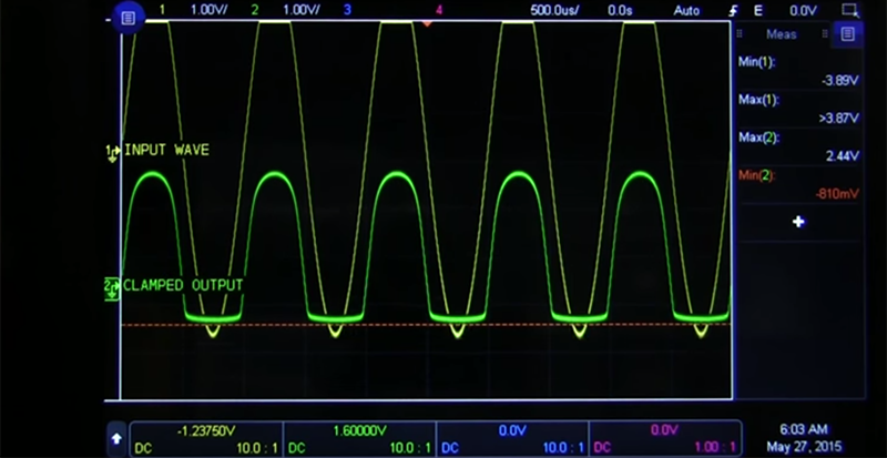
[Afroman] goes over a few of the most useful applications of zeners, including a diode clamping circuit. This circuit will clamp the voltage to a maximum of Vz, helpful when you’re feeding a signal into an analog input. This voltage clamping circuit can be used in some interesting applications. If you feed a sine wave or other signal though the circuit, you can clip the signal.
Zeners can also be used as a very crude, low current, low accuracy power supply. If you’re looking for a voltage regulator for a microcontroller that’s impossibly easy and you’re all out of 7805s, pick up a zener. It’s not the basis of a good power supply, but it does work.


Back in the day, we used to use zener diodes to cap the voltage that the MAP sensors returned to the ECU in our cars when we installed aftermarket turbochargers (and the car didn’t have one to begin with). Fooling the ECU into thinking that it was still at/near its maximum airflow was one part, ramping up the fuel pressure to increase fueling in relation to airflow was the other. We still blew them up, but sometimes it actually took a while.
Even further back in the day, the small Honda motorcycles up until the mid 1980’s used zener diodes to regulate the charging system. Crude but cheap and effective.
“We still blew them up, but sometimes it actually took a while.” My kind of engineering!
Zeners are a nice way of making a tracking voltage regulator, which can be hard to find in a dedicated regulator. Sometimes an IC has two supplies that can’t be more than some small difference apart until the device is “on”: a zener guarantees that.
TI power supply modules (~10 years ago) has Autotrack that you can bus together. They have since added that to some of their chips.
Yeah, it’s fairly common to see it on switching supplies, but on linear supplies it’s harder to find. And then if you want cheap, low current… I searched for a day or so and said “screw it, just use a zener.”
Actually, I should have remembered: those regulators *do not* do what I had said was needed: if you read the datasheet (for e.g. a PTH05020W) they say:
“Note: Due to the under-voltage lockout feature, the output of the module cannot follow its own input voltage during power up. For more information, consult the related application note.”
There are a number of regulators (a TPS74301, for instance, which I looked at) which certainly *look* like they would work: until you read carefully, and find out that it requires a bias voltage be present before the tracking works. Which means now, if you want that function, you need to sequence an *additional* voltage (so ‘turn on bias, turn on core/io and have them track’).
Obviously if you need a large amount of current and a good transient response, then you just eat the additional complexity. But for simple cases the zener eliminates that. (And if you’re wondering what simple case I’m talking about, look at Versatile I/O SPI Flash modules).
You don’t connect the tracking to you input 5V or 12V bus rail. You connect all the Track pins of all the modules together. That’s it. Their is an internal RC generate the ramp that the each of the supply tracks, so all of them follow the same ramp. Obviously the POL waits for the input bus rail to be stabilize and then power up/softstart.
I used these on very complex systems with more than 10 POL at a time. Each of the ASIC insists on their own power sequencing – that was the only way to get them to interconnect and share same POLs. I have my own power supply supevisor/shutdown circuit to coordinate that.
http://www.ti.com/lit/ds/slts213e/slts213e.pdf see page 10 for multiple POL connection. Might want to talk to TI for tech support if you still don’t understand how to use it.
“You don’t connect the tracking to you input 5V or 12V bus rail. You connect all the Track pins of all the modules together. ”
That’s a different problem. That’s generating 2 or more voltages which track each other on startup, rather than a *single* voltage which tracks the input rail. There isn’t a separate module for the core (3.3V) voltage. It comes up how it comes up, and you need to track it. It wouldn’t make sense to have a separate module, running off of 5V, to provide the core voltage for just the SPI flash, just because it needs an I/O voltage which tracks the input, but isn’t going to draw any significant current.
Again, with any case where you’re sourcing significant (100 mA or more) current, using a zener sucks or doesn’t work, so obviously you wouldn’t do it to things like FPGAs or processors or the like. And *usually* in those cases, you’ve got a core and I/O voltage that need to track, and they’re both lower than the input voltage. So yeah, this wouldn’t make sense.
But in this case, the I/O voltage is lower, and the voltage that it needs to track is actually its input rail: and like I said, it’s pretty hard to find a regulator that will track its own input voltage. But a zener will.
Ive been using a zener as a regulator for a few things which were just a single uC and a few MOSFETs. Works wonders on the cheap!
+1 zenar voltage regulators are cheap and easy… and even easier with the on-line calculators like this one…
http://www.calculatoredge.com/electronics/zener.htm
Zeners are also useful as cheap ESD protection devices.
But be cautious if your input signals are fast as the parasitic capacitance of the diode will definitely affect the rise and fall times. If it’s an issue, go with TVS diodes.
http://www.semtech.com/images/promo/What_are_TVS_Diodes.pdf
Agreed. Not suitable for USB or ethernet, fine for UARTs, switches and other low frequency signals. The additional capacitance may even be useful in those cases.
Yeah. Your typical Zener have hundreds of pF vs (tens of pF you normally have for loads and what chips are spec for). So that distorts the signals as well as it is sloooooow for clipping.
Much better to use signal diodes or schottky signal diodes to steer them into a pre-biased zener or voltage rail. Avoid anything that are designed for power supply – zener diodes, rectifying diodes (i.e. 1N400x) – too much capacitance.
Be aware of what the actual clipping voltages are. Read the datasheet as they are usually much higher than you expect!
Wow afroman is still around.
right? Remember his website, with the ripped cardboard and tinfoil? Coolest website ever.
At some point I even created my own 7805 with a zener, an opamp, a MOSFET and some resistors. Worked like a charm.
I have been using them since the early 90’s to prevent latch-up, lock-up, and unwanted code jumping due to ESD directly across microcontrollers. If you have a design that could kill someone in one of those situations, a penny or two zener is well worth avoiding a lawsuit.
TVS’s all the way for ESD protection on any input line from a micro going out to the real world along with 0.01 or 0.1uF chip cap and two S1B clamping diodes between VCC and ground. I plan on 10 cents an I/O pin for any design that goes to the outside world from the micro (think screw terminals on alarm panels, garage door openers and so on).
It’s the only way to get a product certified by those “gorillas” at UL that used to work for American Tourister (go to you tube and type in american tourister gorrila commercial). I poke fun at UL but there are reasons for their testing and having standards.
It isn’t only ESD that affects I/O pins, UL regularly tests for induced noise on I/O lines as well. If something has to work and work under all known conditions, you have to filter and protect your I/O lines. Sometimes it is what I mentioned above, sometimes it also involves the lowly LM339 and/or LM324.
Most micros can now recover from brown out conditions, but back in the day we had to use those on the reset/not reset pin on micros as well.
Most devices now will handle human body models to 8kV, but many UL standards test to 20kV. So if you are just starting out, be aware of it. If what you are designing is something like a kids toy or something else, you can leave these things off, if all it does after an ESD event, means you have to unplug / replug or load / unload batteries. However, people expect things to work. I have learned alot about this in 27 years of engineering.
I am now afraid of my car…LOL.
Those ESD test are brutal. I looked at the schematics when I first joined and notice the capacitors across the LEDs, I figured that they are there to handle the ESD. The PI test guy has a big ESD generator gun with a tip about size of a finger. Any openings that that you can poke a finger near/into, he zap it.
“low accuracy” … well, not exactly, given that all voltage standards except the primary standards use Zeners…